Jual Tanki aspal AMP

Fabrikasi Tanki Aspalt AMP

Perusahaan kami merupakan peresuahan penyedia tanki aspal amp murah dan kontraktor peralatan mesin industri sperti pabrik garmen, pabrik mkanan, pabrik pertambangan dan pabrik aspal amp, perushaan yang memiliki performa dan kualitas di bidangnya selama puluhan tahun di indonesia juga menyedikan atau fabrikasi pemesnan custem tanki aspal untuk amp denganberbagai macam ukuran dan jenis tanki yang di butuhkan dengan kulaitas terbaik dan harga terjangkau.

tentu kita sering dengar mengenai pabrik aspal dan kata lain AMP atau yang di sebut asplat mixing plant, suatu mesin atau alat untuk pengolahan matrial bahan baku menjadi bahan asplat siap pakali di jalan. dari bagian sistem kerja amp banyak terdiri instrumen penting yang harus ada seperti tanki penampungan asplat. kenapa pabrik aspal harus menggunakan tanki penampungan berikut peran penting dari tanki aspal.

Tangki aspal thermal oil

Pengertian penampung tanki aspal

Tangki Aspal merupakan Bagian dari AMP atau Asphalt Mixing Plant yang berupa tangki bekerja untuk menyimpan/menampung Aspal cair panas dari Asphalt Kettle (Ketel Aspal) atau Truk Aspal Curah. Di dalam Tangki Aspal terdapat Heating Pipe yang dialiri oli panas dari Hot Oil Heater. Panas dari Heating Pipe inilah yang membuat temperatur aspal cair panas dalam Tangki Aspal menjadi stabil. Bagian luar dari Tangki Aspal dilapisi Glasswool/Rockwool yangberfungsi sebagai isolator. Aspal cair panas dari Tangki Aspal dipompa ke Timbangan Aspal (Asphalt Weighing) di Main Frame menggunakan Asphalt Supply Pump.

Tangki aspal untuk AMP harus cukup besar sehingga dapat menampung aspal yang memenuhi kebutuhan aspal saat AMP dioperasikan, tentu aspal yang ada di dalamnya dengan mudah dapat terlihat.Pada beberapa AMP terdapat beberapa tangki aspal yang saling berhubungan satu dengan lainnya.Tangki pertama mempunyai fungsi menampung aspal yang baru datang dari pemasok, dan tangki lainnya mempunyai fungsi untuk menampung aspal yang telah dipanaskan dan siap untuk ditimbang dan dimasukkan ke dalam pencampur (blender/pugmill). Setiap tangki harus dilengkapi dengan sebuah alat sensor thermometric yang telah dikalibrasi sehingga temperatur aspal dari tiap tangki akan terkontrol.

Pembuatan tanki Aspal

Aspal harus cukup cair untuk dapat dialirkan dengan baik, oleh karena itu diperlukan penangas aspal. Terdapat beberapa jenis penangas aspal di dalam tangki, antara lain dengan sistim sirkulasi uap panas atau sirkulasi oli panas di dalam tangki aspal atau dapat juga dengan sistim elektrik.

Pada sirkulasi aspal terdapat dua jenis pipa, yaitu pipa pemasok yang berfungsi mengalirkan aspal panas untuk ditimbang dan pipa pengembali yang berfungsi mengalirkan aspal kembali ke dalam tangki.Tangki aspal, pipa pemasok, pipa pengembali, dan timbangan aspal harus mempunyai pelindung panas sehingga dapat menjamin temperatur aspal sesuai dengan yang ditentukan.Pada sirkulasi aspal pipa pengembali harus terletak di bawah pipa pemasok aspal.Untuk mencegah terjadinya kekosongan dalam pipa pengembali aspal, perlu dipasang dua atau tiga buah lubang pada pipa pengembali di atas ambang atas tertinggi aspal dalam tangki.

Tanki Aspal yang tersedia Fabrikasi :

Tangki Aspal 10000 liter/kg
Tangki Aspal 12000 liter/kg
Tangki Aspal 18000 liter/kg
Tangki Aspal 20000 liter/kg
Tangki Aspal 25000 liter/kg
Tangki Aspal 28000 liter/kg
Tangki Aspal 30000 liter/kg
Tangki Aspal 35000 liter/kg
Tangki Aspal 38000 liter/kg
Tangki Aspal 40000 liter/kg
Tangki Aspal 45000 liter/kg
dan masih banyak lagi tentu tidak kami kutip di artikel karna fabrikasi kami bisa custem juga

Berikut sedikit artikel pembahasan menganai tanki aspal AMP semoga bisa bermanfaat bagi saya dan kita semua. apabila ada kebutuhan atau pertanyaan mengenai fabrikasi tanki asplat bisa segaera di diskusikan ke admin kami. dan selain itu kami menjual tanki asplat bisa berikut mesin pemanasnya yaitu unit thermal oil hetae/boiler. lebih jlasnya bisa japri langsung ke nomor.. 081385776935

Jual Perbaikan Cerobong Boiler

Jasa Pembuatan Cerobong Boiler

Perusahaan  Pusat pembuatan steam boiler dan semua jenis boiler, melayani jual jasa pembutan atau perbaikan instrumen pelngkap boiler di antaranya crebong boiler atau chimney. perusahaan kami tokomesinku melayani panggilan jasa perbaikan crobong di seluruh industri di indonesia dengan tenaga ahli yang sudah profesional dan memiliki surat izin khusus untuk pekerja penanagan mesin bejana tekan atau seteam boiler.

water-scrubber

Pengertian Cerobong pada Boiler

Karena undang-undang atau aturan negara kita polusi semakin ketat dari hari ke hari, semua industri yang menggunakan boiler atau tungku yang melibatkan proses melelahkan gas berbahaya ke atmosfer sekitarnya harus memasang cerobong asap dalam proses mereka. Ada juga beberapa undang-undang terkait dengan ketinggian cerobong tergantung pada jenis daerah.

Tokomesinku telah merancang, membuat, dan memasang beberapa cerobong industri di seluruh indonesia. Kami memiliki pengalaman luas dalam mendesain cerobong asap yang melibatkan rancangan perhitungan berdasarkan suhu gas buang di saluran masuk dan saluran keluar cerobong asap .

Kami telah memasok banyak cerobong asap bersama dengan Steam Boiler Assembly kami . Proses umum melibatkan menghasilkan gas buang dari pembakaran bahan bakar baik itu bahan bakar (padat / cair / gas). Kemudian gas buang bergerak dari Boiler ke Air Preheaters dan pengumpul debu. Setelah keluar dari pengumpul debu, gas buang memasuki cerobong asap melalui ID Fan untuk menyimpulkan proses ini sebelum dilepaskan ke atmosfer.

Cimney Cerobong boiler

Cerobong atau chimney pada boiler biasa digunakan untuk mengalirkan gas asap keluar dari ketel uap dengan kecepatan tertentu, dan selain itu digunakan untuk mengatasi getaran–getaran yang terjadi terhadap aliran gas asap, mulai dari rangka bahan bakar atau pembakaran kompor burner, hingga keluar melalui cerobong. Tahapan yang terjadi sepanjang saluran asap, antara lain disebabkan adanya tahanan pada saat gas asap melewati celah–celah diantara pipa didaerah konveksi dan pada pemanas udara, serta untuk membelokkan gas asap sepanjang salurannya, tidak hanya itu juga bila tejadi penyempitan atau masalah saluran gas asap. Hal ini berakibat kecepatan gas yang keluar menjadi berkurang. Dan untuk memperlancar jalanya gas tersebut maka pada saat ditambahkan blower yang membantu pemasukan atau pengeluaran udara.

Definisi Steam boiler mengunakan cerobong

Ketel uap boiler merupakan mesin konversi energi yang mengkonversikan energi kimia bahan bakar menjadi energi panas dari uap melalui proses pembakaran bahan bakar. Ketel uap terdiri dari dua bagian utama yaitu: furnace dan evaporator. Sedangkan komponen lain, yaitu superheater, chimney cerobong asap, ekonomiser dan air heater ,pemanas udara. Ketel uap digunakan secara luas pada proses pembangkit listrik power plan dan pada proses pemanas pada industri kimia. Pada pembangkit listrik ketel uap dihubungkan dengan peralatan lain untuk menghasilkan energi listrik yaitu turbine dan generator. Sebagai mesin konversi energi, ketel uap merupakan mesin yang unggul ditinjau dari kapasitas dan effisiensinya, ketel uap dapat menghasilkan uap sampai 500 ton uap setiap jam. Dari segi bahan bakar ketel uap dapat beroperasi dengan berbagai macam bahan bakar, baik dari bahan bakar padat, sampai bahan bakar gas, minyak ataupun sampah bekas.

Ketel Pipa Air ,Fire Tube Boiler
Pada ketel uap pipa api fluida udara mengalir dalam pipa adalah gas nyala hasil pembakaran, yang membawa energi panas thermal energi, yang segera mentransfernya ke air ketel melalui bidang pemanas heating surfance. Tujuan pipa api ini adalah untuk memudahkan distribusi panas kalori kepada pipa air ketel. Pada jenis ketel pipa api ini dalam penggunaannya berkapasitas dibawah 10 ton perjam tekanan maksimum 24 Kg/cm2, jadi masih tergolong ketel dengan tekanan rendah.yang termasuk ketel ini adalah ketel Cornwall, Lancashire Schots, Cocron dan Ketel lokomotif.

Ketel Pipa Air ,Water Tube Boiler.
Boiler Ketel pipa air adalah ketel air dimana air berada didalam pipa atau tabung, yang dipanasi oleh api atau asap dibagian luarnya. Pada ketel pipa air, fluida yang mengalir dalam pipa adalah air. Energi panas ditransfer dari luar pipa ke air ketel. Kapasitas uap yang dihasilkan bisa mencapai 250 ton/jam.

Kesimpulan Crebong pada Boiler

Setelah kita membaca artikel pembahasan cara kerja boiler dan fungsi cerobong pada boiler tentu sangat penting kita memperhatikan asap sisa udara dari boiler, selain harus menjaga polusi udara untuk efesiensi dan kemanan boiler lebih terjaga. sealin kami membahas pengrtian cerobong pada boiler dan fungsinya kami juga memberi solusi untuk pabrik indutri anda lebih aman dan bisa bekerja secara lancar.

Perusahaan kami bisa mengerjakan jasa perbaikan atau jasa pembuatan unit baru crobong boiler dengan berbagai macam ukuran dan matrial yang di minta sesuai kebutuhan, apabila ada keraguan untuk pengatian crobong yang lama dengan crobong yang baru kami juga bisa melakukan survey pengecekan ke lokasi demi menjaga, mengantisipasi ketidak smaan atau kepuasan pelanggan.

semoga artikel ini bisa bermanfaat bagi sya dan kita semua, apa bila ada tutur kata dan pengetikan di dalam artikel yang tidak sesuai mhon di maklumi. dan jika anda ada untuk diskusi atau membutuhkan pembuatan crebong boilenya bisa hubungi kami di stiap waktu selalu terbuka melayani kebutuhan konsumen. untuk info kontak yang di hubungi..

Zaenal Arifin
Wa. 081385776935

Jual Safty Valve Boiler

Safety Valve Boiler mrek VTV

Distributor penjualan steam boiler di indonesia tokomesinku juga menjual instrumen dari pada mesin boiler, instrumen boiler yang kami jual salah satunya safty valve untuk steam boiler. kami menyedikan berbagai ukuran dan type  valve dengan merek VTV dimana merek valve yang satu ini merupakan produk yang sudah banyak populasinya di indonesia terutama di dunia perindustrian khususnya untuk mesin steam boiler. bagaimana si cara kerja safty valve pada steam boiler berikut akan kami ulas sedikit menganai safty valve untuk boiler.

Safty valve adalah alat yang ber fungsi yang sangat berbeda dari valve-valve lainya. Valve ini buat khusus untuk melepas tekanan berlebih yang ada di hardware dan sistem perpipaan. Untuk mencegah kerusakan pada gear, dan lebih penting lagi cedera pada pekerja, help valve dapat melepas kenaikan tekanan sebelum menjadi lebih ekstrim.

Safty Valve Boiler proses

safty valve menggunakan pegas baja, yang secara otomatis akan terbuka jika tekanan mencapai level yang berlebih. Level tekanan pada valve ini bisa diatur, sehingga bisa ditentukan pada level tekanan berapa valve ini akan terbuka. Ketika tekanan kembali ordinary, alleviation valve secara otomatis akan tertutup kembali.

safty valve adalah jenis valve yang mekanismenya secara otomatis melepaskan zat dari heater, Bejana tekan, atau suatu sistem, ketika tekanan atau temperatur melebihi batas yang telah ditetapkan.

 Safty valve pada Steam Boiler

Salah satu jenis perangkat keamanan otomatis yang sangat dibutuhkan pada sistem uap adalah safety valve pada sistem boiler, Safty valve akan bekerja melindungi alat dan perangkat dari bahaya yang diakibatkan oleh temperatur dan gaya karena tekanan uap boiler berlebih dalam sistem. maka, safty valve bisa membuka dan membuang steam yang berlebih dari boiler apabila tekanan dan temperatur di dalam sistem uap melampaui batas set poin . tidak hanya itu safty valve juga berfungsi membuang uap yang telah menjadi kondensat agar tidak masuk ke turbin dan menyebabkan korosi pada turbin.

Bisa juga valve digunakan pada sistem heater untuk ruang evaporator valve harus sesuai dengan perkembangan sistem uap terbaru. safty valve harus ditinjau ulang secara periodik tergantung standar unit, rekomendasi jaminan perusahaan dan hukum pemerintah. The American Society of Mechanical Engineers (ASME) merupakan departemen yang mengatur mengenai wellbeing valve. ASME telah memperbaharui heater dan bejana bertekanan untuk security valve. Di United States, hal yang menjadi pertimbangan besar untuk wellbeing valve adalah memilih ukuran tepat yang diikuti dengan instalasi yang benar.

Pengetahuan isntalasi safty valve boiler :

Perlu di ketahui Set point dari safety valve disarankan agar delta yang terbentuk antara tekanan operasi uap dan yang diatur adalah minimal 20%. Ketika mempertimbangkan aliran bawah pada safety valve dari control valve tekanan uap, kapasitas total dari safety valve pada set point harus melampaui kapasitas aliran maksimum control valve tekanan uap. Tekanan steam masuk ke valve harus dihitung pada settingan maksimum safety valve dari sumber suplai steam Ukuran safety valve tidak melebihi desain perhitungan. Safety valve yang berlebihan pada kasus ini tidak baik karena dapat menyebabkan suara yang tidak enak didengar, kebocoran dan kerusakan pada safety valve. Single safety valve tidak dapat dilakukan karena kapasitasnya yang besar, kondisi fisik safety valve yang terbatas dan pertimbangan ekonomi. Tekanan yang diatur pada safety valve sebaiknya diatur berada pada atau dibawah titik Maximum Allowable Working Pressure dari komponen dengan set poin terendah pada sistem. Di sisi lain, dua komponen pada sistem yang sama dengan tekanan yang berbeda, akan dilindungi oleh perangkat keamanan.

Sepesifikasi Safty Valve VTV

Safty Valve VTV 6301

Safty Valve VTV

Application and Kinds of Execution Si 6301 – for air, steam and other neutral gases and vapours.
Working temperature : from -40C up to +400C Si 6301C – Valves with reduction of disc leap to the value 0.12 of seat diameter d, applied water and other neutral liquids.
Working temperature: from -40C up to + 400C

For temperature above 350C the execution with insert Si 6302 W is recommended.
Applications for temperature under -10C valid are restrictions according to AD 2000 Merkblatt W10

Safty Valve VTV 6302

pressure-safety-valve

Application and Kinds of Execution Si 6302 – for air, steam and other neutral gases and vapours. Working temperature : from -40C up to +400C
Si 6302C – Valves with reduction of disc leap to the value 0.12 of seat diameter d, applied water and other neutral liquids. Working temperature: from -40C up to + 400C

For temperature above 350C the execution with insert Si 6302 W is recommended. Applications for temperature under -10C valid are restrictions according to AD 2000 Merkblatt W10

info lebih lanjut
Wa. 081385776935

Jual Valve VTV Jkarta

Distributor Valve VTV di Indoneisa

Perusahaan fabrikasi boiler dan thermal oil di indonesia, tokomesinku juga menyediakan jual  valve VTV untuk indutri dan pabrik perkebunan, valve yang kami sedikan adalah valve merek VTV yang dimna valve tersebut sudah memiliki gudang dan pusat di indonesia tentu setock juga banyak. untuk menegenal lebih dalam tentang valve, sebenarnya valvi itu ada banyak jeniy dan bebagai fungsinya juga.

GALOBE VALVE VTV

Valve VTV atau katup merupan sebuah perangkat yang biasanya terpasang pada sistem pemipaan, yang berguna sebagai pengatur dan mengarahkan laju aliran fluida dengan cara membuka, menutup atau menutup sebagian aliran fluida. Katup memiliki peran penting dalam suatu industri seperti mengontrol air untuk keperluan pemanasan air pada steam boiler.

Globe Valve VTV dapat dioperasikan secara manual, baik dengan menggunakan pegangan, tuas pedal dan lain sebagainya. Selain dioperasikan secara manual, valve dapat dioperasikan secara otomatis dengan menggunakan prinsip tekanan dan suhu. Perubahan tersebut akan mempengaruhi diafragma, pegas atau cylinder sehingga secara otomatis akan menggerakan katub dengan sistem buka tutup. tentu valve memiliki banyak jenis dan type lainya yang mungkin masih banyak di antara kita yang belum begitu memahami, kali ini akan kami bahas sdikit mengenai valve jenis Globe atau Globe valve.

Pengertian Umum Globe valve

Globe Valve merupakan suatu valve yang mempunyai arah gerak linier begitu dirancang sebagai halting ( menghentikan arus), membuka arus dan mengatur arus. Plate globe valve bisa benar-benar menutup sebuah arus. Untuk globe valve biasa (konvensional) dapat digunakan sebagai isolasi dan throttling administration. Meskipun valve jenis ini menunjukkan sedikit lebih tinggi angka penurunan tekanan di banding dengan valve jenis lain ( door valve, plug dan ball valve). Globe valve secara dasar di desain untuk mengontrol aliran. Panjang jangkauan (go) control aliran, penurunan tekanan dan obligation harus menjadi pertimbangan dalam merancang pembuatan globe valve agar tidak terjadi kegagalan framework. Pada umumnya tekanan diferensial (differential weight) maksimum pada plate tidak boleh melebihi 20% dari tekanan maksimum upstream atau sekitar 200psi (1380kPa). Namun untuk Janis globe valve dengan list khusus mampu bekerja melebihi besar tekanan tersebut.

Adapan Jenis-Jenis Globe valve yang perlu kita pahami sebagai berikut:

  1. Z-Body desain adalah tipe yang paling umum yang sering dipakai, dengan diafragma berbentuk Z. Posisi dudukan disk horizontal dan pergerakan batang disk tegak lurus terhadap sumbu pipa atau dudukan disk. Bentuknya yang simetris memudahkan dalam pembuatan, instalasi maupun perbaikannya.
  2. Y-Body desain adalah sebuah alternatif untuk high pressure drop. Posisi dudukan disk dan batang (stem) ber sudut 45˚ dari arah aliran fluidanya. Jenis ini sangat cocok untuk tekanan tinggi
  3. Angle-Body desain adalah modifikasi dasar dari Z-Valve. Jenis ini digunakan untuk mentransfer aliran dari vertikal ke horizontal.

Sepisikasi Matrial Globe Valve VTV

VTV GLOBE VALVE ANSI CLASS 150 – GBV 201

VTV Globe Valve GBV-201
Design : DIN 3356
Face to face : DIN 3202
Flanges :DIN 2501 DIN 2547, DIN 2526 FORM E, BW TO DIN 3239
Testing : DIN 3352 DIN 3230
Rating P – T : DIN 2401

VTV VALVE BELLOW SEAL GLOBE VALVE GBV-202

globe-page-below-seal-globe-1

Design : DIN 3356
Face to face : DIN 3202
Flanges : DIN 2501 DIN 2547, DIN 2526 FORM E, BW TO DIN 3239
Testing : DIN 3352, DIN 3230
Rating P – T : DIN 2401
Suitable Medium : W.O.G

VTV VALVE GBV – 201 CLASS 150 CAST STEEL

VTV Valve GBV 201 - cast steel

Design : BS 1873
Face to face : ASME B16.10
Flanges : ASME B16.5, BW ENDS TO ASME, B16.25
Testing : API 598, API 6D, BS 6755
Rating P-T : ASME B16.34
Suitable Medium : W.O.G

VTV VALVE ANGLE GLOBE VALVE GBV-203

Globe valve GBV-203

serving Multi-National end users in a wide range of applications in many industries including:

Palm Oil and Refinery Plant
Petrochemical
Food Industries
Heating
Cooling System

Design : DIN 3356
Face to face : DIN 3202
Flanges : DIN 2501, DIN 2547, DIN 2526 FORM E, BW TO DIN 3239
Testing : DIN 3352, DIN 3230
Rating : DIN 2401
Suitable Medium : W.O.G

Demikian artikel yang dapat kami sampaikan semoga bisa bermanfaat buat sya dan kita semua. apabila ada kebutuhan atau pertanyaan konsultasi mengenai valve bisa segera hubungi sales kami di . 081385776935

Distributor Pompa Ebara

Perusahaan distributor pompa

Perusahaan fabrikasi steam boiler dan thermal oil hetaer tokomesinku juga menjual berbagai jenis model pompa ebera untuk industri maupun pergedungan. perushaan kami selain menjual produk pompa ebara kami melayani untuk pemasangan di seluruh indonesia dengan tenaga ahli dan mahir di bidangnya.

jual pompa ebara

pompa ebara sendiri sering kita jumpai di berbagai industri contoh nya oil and gas, industri makanan dan berbagai pabrik lainya. perlu di ketahui pompa ebara brand dari negara jepang dan sekarang sudah di produksi di indonesia, guna untuk membermudah setock dan daya tarik kemampuan negara berkembang.

Pompa Ebara Centrifugal adalah pompa yang withering banyak digunakan, ia memiliki kelebihan diataranya karena peng-oprasiannya yang mudah, upkeep yang tidak terlalu mahal, tidak berisik dan lain sebagainya. Sebelum ke cara kerja radiating siphon, ada baiknya kita memahami prinsip kerja dari pompa terlebih dahulu. Pompa, adalah alat untuk mengalirkan fluida cair. Bedanya dengan blower, blower biasanya digunakan untuk mengalirkan fluida yang compressible, fluida yang dapat di mampatkan seperti udara.

Cara Kerja Pompa

Prinsip kerja pompa adalah ia mencipatakan tekanan vakum pada inletnya, yang akhirnya menyerap fluida ke dalam pompa, kemudian mendorongnya melalui keluaran, release. Ada dua jenis pompa sebenarnya, yaitu positif removal siphon dan satu lagi jenis dynamic, diffusive siphon ini masuk dalam jenis pompa yang motor

distributor pompa ebara

Pada pompa diffusive, ia memanfaatkan gaya radial. Seperti apa gaya diffusive? Coba kita buat sedikit try untuk memahami gaya radiating. Misalnya kamu punya sebuah wadah, coal misalnya. Kamu putar di sekitar kepalamu, ketika putaran itu semakin kencang, di tanganmu akan terasa tertarik oleh gaya dari ash yang kamu putar. Semakin kencang putarannya, semakin besar gayanya. Gaya pada lenganmu itulah gaya radial.

Kalau di definisikan, gaya sentrifugal adalah gaya gerak melingkar yang berputar menjauhi pusat lingkaran, dimana nilainya adalah positif. Coba lihat gambar di atas, ketika impeller (baling) berputar maka air akan terdorong di impeller lewat gaya sentrifugal dan akhirnya keluar di saluran release, sedangakan pada suctionnya menjadi negative weight nya yang menyebabkan air jadi terisap pada suction nya.

Type Pompa Ebara dan spesifikasi

CENTRIFUGAL PUMP :
Merk : EBARA
Type : 80X65 FS2H511
Cap. : 800 Ltr/ m
Head : 40 m
Power : 11 KW/ 15 HP/ 380 V/ 3 Phase/ 2 Pole/ 50 Hz/ 3000 Rpm

CENTRIFUGAL PUMP :
Merk : EBARA
Type : 65X50 FS2H55.5
Cap. : 29.5 m3/ h
Head : 30.5 m
Power : 5,5 KW/ 7,5 HP/ 380 V/ 3 Phase/ 2 Pole/ 50 Hz/ 2950 Rpm

SELF PRIMMING PUMP :
Merk : EBARA
Type : SQPB 50
Discharges : 2 “
Meterial : Cast Iron

Merk : EBARA
Type : SQPB 80
Discharges : 3 “
Meterial : Cast Iron

SOLAR PUMP/ FEUL PUMP ( CENTRIFUGAL ) :
Merk : EBARA
Type : 80X65 FS4H51,5
Cap. : 500 Ltr/ m
Head : 10 m
Sealling : Mechanical Seal ( Special Order )
Power : 1,5 KW/ 2 HP/3Phase/ 4 Pole/ 380 V/ 50 HZ/ 1500 Rpm

CENTRIFUGAL PUMP :
Merk : EBARA
Type : 50 x 40 FSH
Suction : 2”
Discharge : 1 ½”

Merk : EBARA
Type : 65 x 50 FSH
Suction : 2 ½ ”
Discharge : 2”

CENTRIFUGAL PUMP :
Merk : EBARA
Type : 65X50 FSH
Cap. : 500 Ltr/ m
Head : 40 m
Power : 10 HP/ 380 V/ 50 HZ/ 3 Phase/ 2900 Rpm

CENTRIFUGAL PUMP :
Merk : EBARA
Type : 50 x 40 FSH
Cap : 18 M3/H
Head : 30 M
Power : 5 HP/ 380 V / 50 HZ/ 2950 Rpm

Merk : EBARA
Type : 50 x 40 FSH
Cap : 18 M3/H
Head : 40 M
Power : 7,5 HP/ 380 V / 50 HZ/ 2950 Rpm

CENTRIFUGAL PUMP :
Merk : EBARA
Type : 50X40 FSH
Cap. : 100 Ltr/ m
Head : 30 m
Power : 3 HP/ 380 V/ 50 HZ/ 3 Phase/ 2900 Rpm

Merk : EBARA
Type : 50X40 FSH
Cap. : 100 Ltr/ m
Head : 40 m
Power : 5 HP/ 380 V/ 50 HZ/ 3 Phase/ 2900 Rpm

CENTRIFUGAL PUMP :
Merk : EBARA
Type : 125X100 FS4K
Cap. : 100 m3/ h
Head : 25 m
Power : 11 KW/ 15 HP/ 380 V/ 3 Phase/ 50 HZ/ 1500 Rpm

SUMP PIT PUMP :
Merk : EBARA
Type : 50 DL
Cap. : 10 m3/ h
Head : 20 m
Power : 3,7 KW/ 5 HP/ 380 V/ 50 HZ/ 4 Pole/ 1450 Rpm

WATER PUMP :
Merk : EBARA
Type : 65X50 FS2J511
Cap. : 20.000-24.000 Ltr/ H
Pressure : 6 Bar
Power : 11 KW/ 15 HP/ 440 V/ 60 HZ/ 2 Pole/ 2900 Rpm

SOP HWG Boilers

Boiler Safety Operation Standards

INDUSTRIAL SAFETY – Boiler Safety Operation Standards

Boiler: A Steam Boiler

SOP HWG Boilers
SOP HWG Boilers

Boiler is a closed vessel where the combustion heat is flowed into water to form hot water or steam in the form of work energy. Water is a useful and inexpensive medium for transferring heat to a process. Hot water or steam at a certain pressure and temperature has an energy value which is then used to transfer heat in the form of heat energy to a process. If the water is boiled until it becomes cold, the volume will increase about 1600 times, producing power that resembles explosive gunpowder, so the boiler system is a device that must be managed and maintained very well.

Boiler Work Process

The heat energy generated in the boiler system has a value of pressure, temperature, and flow rate that determines the utilization of  steam  to be used. Based on these three things the boiler system recognizes the state of  low pressure (low pressure / LP) , and  high pressure (high pressure / HP) , with the difference that the utilization of steam  coming out of the boiler system is utilized in a process to heat the liquid and run a machine  (commercial and industrial boilers),  or generate electrical energy by converting heat energy into mechanical energy then turning a generator to produce electrical energy  (power boilers). However, there is also a combination of the two boiler systems, which utilize high-temperature pressure to generate electricity, then the remaining  steam  from the turbine with a low-pressure state can be utilized in industrial processes with the help of  boiler heat recovery.

The boiler system consists of a feed water system, a steam system  , and a fuel system. The feed water system provides water to the boiler automatically according to steam needs  . Various taps are provided for maintenance and repair of feed water systems, feed water handling is needed as a form of maintenance to prevent damage to the steam system  . The steam system  collects and controls steam production   in the boiler. Steam is flowed through the piping system to the user’s point. In the whole system, steam pressure  regulated using a faucet and monitored with a pressure monitor. Fuel systems are all equipment used to provide fuel to produce the heat needed. The equipment required in the fuel system depends on the type of fuel used in the system.

Before explaining the diversity of boilers, it is necessary to know the components of the boiler that support the creation of  steam , the following components of the boiler:

  1. Furnace

This component is a place for burning fuel. Some parts of the  furnace  include:  refractory , fireplace room,  burner ,  exhaust for flue gas ,  charge and discharge door  .

  1. Steam Drum

This component is a hot water reservoir and steam generator  . Steam is  still saturated ( saturated steam ).

  1. Superheater

This component is a place for drying  steam  and is ready to be sent through the  main steam pipe  and ready to drive a steam turbine or run an industrial process.

  1. Air Heater

This component is a heating chamber that is used to heat the outside air that is absorbed to minimize the humid air that will enter the furnace.

  1. Economizer

This component is a heating chamber that is used to heat water from condensed water from the previous system and new feed water.

  1. Safety valve

This component is a steam exhaust   in the event that the steam pressure   exceeds the boiler’s ability to withstand steam pressure  .

  1. Blowdown valve

This component is a channel that functions to remove deposits that are inside the steam pipe  .

Boiler Classification

After knowing the short process, the boiler system, and the components forming the boiler system, it is necessary to know the diversity of the boiler. Various forms of boilers have evolved following technological advances and evaluations of previous boiler products that are affected by boiler exhaust gases that affect the environment and what kind of steam products will be produced. The following classification of boilers that have been developed:

Based on the pipe type:

  1. Fire Tube

Fire pipe boiler types have the following characteristics: produce low steam capacity and pressure .

How it works: the ignition process occurs in the pipe, then the heat generated is delivered directly into the boiler that contains water. The size and construction of the boiler affect the capacity and pressure generated by the boiler.

  1. Water Tube

The type of water pipe boiler has the following characteristics: high steam capacity and pressure .

How it works: the ignition process occurs outside the pipe, then the heat generated heats the pipe filled with water and before the water is conditioned first through an economizer, then the steam produced first is collected in a steam- drum. Until the pressure and temperature match, through the secondary superheater and  the new primary superheater, steam is released into the main distribution pipe. In a water pipe, running water must be conditioned to minerals or other contents that are dissolved in the water. This is the main factor that must be considered for this type.

Table 1.1. Boiler advantages and disadvantages based on pipe type.

No. Boiler Type The advantage Loss
1 Fire Tube The installation process is easy and fast, does not require  special settings Steam operating pressure is  limited to 18 bar low pressure
The initial investment of this boiler is cheap Steam capacity is   relatively small (13.5 TPH) when compared to a water tube
The shape is more compact  and  portable The kiln is difficult to reach for cleaning, repair and condition checking.
Does not require a large area for 1 HP boiler The efficiency value is low, because a lot of heat energy is wasted directly into the stack
2 Water Tube Large steam capacity   up to 450 TPH The construction process is more detailed
Operating pressure reaches 100 bar Initial investment is relatively more expensive
The efficiency value is relatively higher than the fire tube boiler The handling of water entering the boiler needs to be maintained, because it is more sensitive for this system, it needs supporting components for this
The furnace is easy to reach for inspection, cleaning and repair. Being able to produce greater steam capacity and pressure   , the construction requires a large area

Based on the fuel used:

  1. Solid Fuel

Solid fuel boiler types have the characteristics: the price of combustion raw materials is relatively cheaper compared to boilers that use liquid and electric fuels. The efficiency value of this type is better when compared to electric type boilers.

How it works: heating that occurs due to combustion between mixing of solid fuels (coal, baggase, rejected products, municipal waste, wood) with oxygen and heat sources.

  1. Oil Fuel

The type of liquid fuel boiler has the following characteristics: the price of the most expensive combustion raw material compared to all types. The efficiency value of this type is better when compared with solid fuel and electricity boilers.

How it works: heating that occurs due to combustion between the mixing of liquid fuels (diesel, IDO, residues, kerosene) with oxygen and heat sources.

  1. Gaseous Fuel

The type of gas fuel boiler has the following characteristics: the price of the combustion raw material is the lowest compared to all types of boilers. The efficiency value of this type is better when compared to all types of boilers based on fuel.

How it works: combustion that occurs due to mixing of gas fuel (LNG) with oxygen and heat sources.

  1. Electric

This type of electric boiler has the characteristics: the price of heating raw materials is relatively cheaper compared to boilers that use liquid fuel. The efficiency value of this type is lowest when compared with all types of boilers based on fuel.

How it works: heating that occurs due to a source of electricity that supplies a source of heat.

Table 1.2. Boiler gains and losses based on fuel.

No. Boiler Type The advantage Loss
1 Solid Fuel Raw materials are easy to get. Residual combustion is difficult to clean
Cheap construction. Difficult to get good raw materials.
2 Oil Fuel Not much combustion left over and easier to clean. The price of the most expensive raw materials.
The ingredients are easy to get. Expensive construction.
3 Gaseous Fuel The cheapest fuel prices. Expensive construction.
The best value is its efficiency. Difficult to obtain raw materials, there must be a distribution channel.
4 Electric The easiest maintenance. The worst value efficiency.
Easy construction and easy to get the source. The lowest combustion temperature.

Based on the use of the boiler:

  1. Power Boiler

This type of power boiler has characteristics: its main use is as a steam generator as a power plant, and the remaining steam is used to run industrial processes.

How it works: the steam produced by this boiler uses a type of water tube boiler, the resulting steam has a large pressure and capacity, so it is able to turn steam turbines and generate electricity from generators.

  1. Industrial Boiler

Industrial boiler types have characteristics: their main use is as a producer of steam or hot water for running industrial processes and as an additional heater.

How it works: steam produced by this boiler can use the type of water tube or fire tube boiler, the resulting steam has a large capacity and moderate pressure.

  1. Commercial Boiler

This type of commercial boiler has characteristics: its main use is as a producer of steam or hot water as a heater and in addition to running commercial operations.

How it works: steam produced by this boiler can use a type of water tube or fire tube boiler, the resulting steam has a large capacity and low pressure.

  1. Residential Boiler

This type of residential boiler has characteristics: its main use is as a producer of steam or low pressure hot water that is used for housing.

How it works: the steam produced by this boiler uses the type of fire tube boiler, the resulting steam has a low pressure and capacity

  1. Heat Recovery Boiler

The type of heat recovery boiler has the characteristics: its main use as a producer of steam from unused hot steam. The results of this steam are used to run industrial processes.

How it works: steam produced by this boiler uses a type of water tube boiler or fire tube boiler, the resulting steam has a large pressure and capacity.

Table 1.3. Boiler gains and losses based on utility.

No. Boiler Type The advantage Loss
1 Power Boiler Can produce electricity and the remaining  steam can run industrial processes. Initial construction is relatively expensive.
Steam  produced has a high pressure Safety factors need to be considered.
2 Industrial Boiler Easier boiler handling. Steam  produced has a low pressure.
Initial construction is relatively inexpensive.
3 Commercial Boiler Easier boiler handling. Steam  produced has a low pressure.
Initial construction is relatively inexpensive.
4 Residential Boiler Easier boiler handling. Steam  produced has a low pressure.
Initial construction is relatively inexpensive.
5 Heat Recovery Boiler Easier boiler handling. Steam  produced has a low pressure.
Initial construction is relatively inexpensive.

Based on boiler construction:

  1. Package Boiler

The type of boiler package has characteristics: boiler assembly is carried out at the manufacturing plant, direct delivery in the form of a boiler.

  1. Site Erected Boiler

The type of site erected boiler has the following characteristics: boiler assembly is carried out at the site where the boiler is to be built, deliveries are carried out per component.

Table 1.4. Boiler gains and losses based on construction.

No. Boiler Type The advantage Loss
1 Package Boiler Easy shipping. Limited pressure and work capacity.
It takes a short time to operate after sending. Boiler components depend on the boiler manufacturer.
2 Site Erected Boiler Work pressure and capacity can be adjusted according to desire. Difficult to send, expensive cost.
Boiler components can be integrated with other manufacturers. It takes quite a long time after the boiler stands, after the shipping process.

Based on boiler working pressure:

  1. Low Pressure Boilers

Low pressure boiler type has characteristics: this type has an operating steam pressure of less than 15 psig or produces hot water with pressure below 160 psig or temperature below 250 0 F

  1. High Pressure Boilers

High pressure boiler type has characteristics: this type has an operating steam pressure above 15 psig or produces hot water with pressure above 160 psig or temperatures above 250 0 F

Table 1.5. Boiler gains and losses based on working pressure.

No. Boiler Type The advantage Loss
1 Low Pressure Low pressure so that the handling is not too complicated The resulting pressure is low, it cannot generate electricity.
The area required is not too large, and the construction cost is not more expensive than a  high pressure boiler
2 High Pressure The resulting pressure is high so that it can generate electricity and the rest can be recycled to operate industrial processes High pressure so that the handling needs to be considered safety aspects.
The area required is large and the construction cost is more expensive than a  low pressure boiler

Based on how to burn fuel:

  1. Stoker Combustion

Stoker combustion type has the following characteristics: this type utilizes solid fuel to ignite, solid fuel is put into the combustion chamber via conveyor or manually. This type has combustion residue that must be handled in the form of bottom ash or fly ash  which can pollute the environment.

  1. Pulverized Coal

How it works: this process destroys coal with a ball mill or roller mill so that coal has a size of less than 1 mm. then this powdered coal is sprayed into the combustion chamber.

  1. Fluidized Coal

How it works: this process destroys coal with a crusher, so that coal has a size of less than 2 mm. In this process combustion is carried out in a layer of sand, coal will immediately burn if it hits the sand.

  1. Firing Combustion

Firing type has characteristics: this type utilizes liquid, solid, and gas fuels to do combustion, heating which occurs more evenly.

How it works: liquid fuel used as preliminary firing fuel is put into the combustion chamber through an oil gun . After reaching the appropriate temperature, combustion is taken over by coal nozzle or gas nozzle .

 Table 1.6. Boiler gains and losses based on combustion.

No. Boiler Type The advantage Loss
1 Stoker Combustion The construction is relatively simple. More waste is produced by combustion
The resulting heat is less even if there are no supporting components.
Relatively low efficiency
2 Pulverized Relatively high efficiency The construction is complicated and requires expensive investment funds.
The combustion process is more evenly distributed in the furnace.
3 Fluidized Bed Relatively high efficiency The construction is complicated and requires expensive investment funds.
The combustion temperature does not reach 1000  0 C so it does not cause NO X
4 Firing Less waste produced by combustion Construction is relatively complicated, it needs a  nozzle.
The heat is produced more evenly
Relatively better efficiency

Based on the boiler constituent material:

  1. Steel

The type of boiler made of steel has characteristics: the main raw material for boilers is made using steel in the steam area .

  1. Cast Iron

The type of boiler made from cast iron has the following characteristics: the main raw material of the boiler is made using cast iron in the steam area .

Table 1.7. Boiler gains and losses based on material.

No. Boiler Type The advantage Loss
1 Steel Strong and durable. Cost is relatively expensive.
Steam can be used  for high pressure. More complicated construction.
2 Cast Iron The cost is relatively cheap. Vulnerable and easily damaged.
Simpler construction. Could be loaded with  steam  for a limited pressure.

Boiler safety

600 MW PLTU boiler

Boiler Protection / Safety Function

Boiler safety is intended to maintain and avoid more serious interference with the boiler and its supporting tools, which results in a decrease in boiler capability, or damage to equipment.

Basic principles

The basis of boiler protection and its auxiliary equipment is that the safety device must be able to guarantee the continuity of the boiler’s steam production service.

Protection

A boiler needs safety to maintain the reliability of operation in a long period of time. This boiler safety system in general will describe the safety of the boiler from corrosion, overheating and thermal stress that is caused during the process of startup, normal operation and shutdown.

Boiler vent must be opened during the filling process so that air in the boiler tube can be removed, the aim is to reduce the possibility of corrosion due to oxidation of air trapped in the boiler tube other than air. It also can cause cavitation and water hammer. Before operating the boiler must be rinsed (purge) from the used gas that accumulates in the combustion chamber is important because the waste gas from the combustion that is not wasted will form a hot gas that can cause an explosion in the room at the boiler ignitor startup because during this period many combustible possibilities occur and explosive due to frequent ignitor ignition failures and unstable binding conditions.

Boiler areas that require special attention include:

Economizer

Feedwater is not always added when raising the boiler pressure because the water in the boiler always circulates naturally. But without the presence of feedwater in the filling water will not flow to the economizer. Economizer is secured from the formation of feedwater evaporation in the tube, because the steam trapped inside can cause water hammer, thermal shock and can cause fluctuations in drum level control. To safeguard this problem there needs to be a continuous flow of circulation from the economizer inlet header to one of the downcomers. This valve must be opened when the boiler is experiencing interference with feedwater flow control, the aim is to avoid the evaporation process in the economizer tube due to the cessation of natural circulation. Economizer is subject to both internal and external corrosion. Internal corrosion can be prevented by maintaining PH feedwater between 8 and 9 by chemical injection. External corrosion can be caused by the occurrence of condensation between the low temperature of the feedwater and the high temperature of the combustion gases that pass through the economizer. Overcoming this problem by keeping the economizer in an area far from the dew point, this case must be avoided during the startup process and after the unit is loaded.

Furnace

Furnace is a part that requires serious attention. Because it deals with the problem of vapor pressure and steam temperature and combustion chamber temperatures are very high. Factors of concern are:


Boiler operating pressure Boilers must not operate above their working pressure and never exceed their design pressure.
– Balance balance firing operation
This relates to the heat generated by combustion of the combustion chamber in the case of imbalance firing, which will cause disruption of the natural circulation process and interference with the tube due to overheating.

Steam Drum

During normal operating conditions pressure on the drum and drum level and water quality must always be controlled. The surface of the steam drum is very high, so at startup and shutdown the temperature difference in this area must be considered, namely the difference between the top and bottom should be as small as possible in this case it is important to maintain the occurrence of thermal stress on the steam drum.

Limitations that must be considered include:
– When there is a change in the phases of water and steam in the steam drum.
– The difference between top and bottom does not exceed the maximum setpoint of 50 0C for startup and 100 0C for shutdown.

Superheater

Superheater located in an area where heat transfer by convection induction attracts quite serious attention because it is related to the condition of the steam temperature and the safety temperature of the metal tube. overheating due to disrupted production and vapor flow while the combustion gas stream passing through the high induction convection area.

Superheater safety limits include:
– Main steam temperature must always be controlled
– Combustion conditions must be balanced firing / adjusted according to its formation
– Thermocouple superheater exit must be monitored
– Gas temperature superheater entry area must be limited during startup to normal operating unit conditions.

Boiler Safety Mode Operation

Safety Directly

  1.  Safety Valve

Before the boiler is declared ready for operation, the safety valve must be checked and if necessary reset in accordance with the working area. This procedure is very important considering that after the boiler firing will produce pressure. This vapor pressure can determine that the safety valve serves as a safety against the occurrence of excess vapor pressure produced by the boiler.

  1.  Relief Valve

Relief valve can be classified as a safety as well as a safety valve, but this relief valve serves as a limiting or maximum pressure safety in the liquid work area. The use of relief valve is placed in the following areas:
– Header reheat / HP bypass spray water
– Header auxiliary steam spray
– Ignitor oil level header
– Heavy fuel oil level header

Indirectly Security

  1.  Pneumatic Valve

The pneumatic valve as well as the safety valve serves as a safety for over steam pressure on the boiler only equipped with a pressure sensor which is conveyed through an electronic signal to the electro mechanical to open the pilot valve.

  1. Safety Boiler Drum Level

Serves to control the level of water level on the boiler drum as a safety for the occurrence of “high level drum boiler trip” and “low level drum boiler boiler”.
The reason for securing a “high level drum trip boiler” is to secure the boiler drum from carrying over in the drum which will result in deposits in the superheater area and turbine blade. Deposits will inhibit the heat transfer of the superheater which results in overheating of the superheater tube and the turbine blade will cause unbalance and vibration of the turbine.
While the condition of “low level drum trip boiler” can cause disruption of natural circulation which will result in overheating in the steam drum and steam production is inhibited.

  1. Safety of the Boiler Furnace

Serves to control the pressure of the combustion chamber / boiler as a safety for the occurrence of:
– Furnace pressure & gt; max
– Furnace draft & gt; max
In connection with the type of boiler with a balance draft design where the design pressure allowed is -10mmWg, this is to ensure the stability of the combustion process. Transportation of coal fuel to the combustion chamber and the process of removing coal ash from inside the combustion chamber to a dust catcher etc. If the security limits are exceeded and distorted, the above process will be disrupted.Things that must be maintained to avoid the above conditions are by:
1) Check the water seal through level on the bottom hopper boiler must be in a position above the normal level. Check LCV and bypass valve water supply.
2) Check the boiler manhole condition before the boiler startup must be in a closed condition including desorvation door.
3) The water level at the SDCC boiler bottom is normal.

  1. Main Steam Temperature Boiler Safety

Its function is to control the high temperature of the main steam coming out of the second level superheater as a safety for the main steam temperature to exceed the allowable design limit.
This security is intended to avoid the occurrence of thermal stress in a first level turbine due to the temperature difference that is too high between the temperature of the main vapor entering with the metal temperature at the turbine blade. In addition to avoiding material fatigue in superheater tubes due to steam temperatures that exceed the maximum capacity of superheater tubes.

  1. Safety of Total Air Flow

Serves to secure the total amount of air entering the windbox / combustion chamber during the boiler purification process. At the time of boiler startup and normal operation must meet the total flow amount greater than the minimum (& gt; 30% when the boiler purge).
At the time of flushing the boiler we expect all the combustion gases that have accumulated in the combustion chamber and exhaust gases to be pushed / released by air in the amount of & gt; 30% or about 600 tons / hour to be discharged into the outside air at least gases remaining clean combustion within 3 minutes (design) then safeguarding at startup and normal operation Toral air plays a role as combustion air so that when the total combustion air is at least 30% then the amount of ratio between air and fuel will not we are absolutely certain that we are worried about repeated ignition failures and one of the causes of combusable in flue gas.

  1. Safeguarding the Air Pressure Header Instrument

Instrument air is a major requirement in the pneumatic power control system. The instrument air supply must be properly maintained and very special considering that the source of power for all turbine boiler controls and its assistants lies in the continuous reliability of the instrument air supply and its working pressure.
Considering the virtue and function of the instrument air as a source of power for all turbine boiler controls and assist equipment, if air pressure drops below its working point, this will cause all pneumatic control functions to cease and will cripple the operation of the boiler and turbine.

Anticipate when an instrument low pressure alarm occurs, including:
– Immediately open the SAC backup valve to the instrument air header.
– Immediately check the condition of the instrument air compressor and its supply process.
– Localize the possibility of instrument air leakage on all lines.
– Localize the possibility of an open air drain / vent valve.

  1. Security Pressure Cool Scanner

Its function is to secure the cooling system on the flame sensor scanner. The importance of flame detection in a boiler to ensure the existence of combustion, so that there will be no buildup of fuel due to failure of ignition. The flame detector is secured from the heat of the combustion chamber by providing cooling in the form of pressurized air seals on the entire surface of the fire detector.

The disruption of this cooling system will result in a melting point on the flame detector because there is direct contact between the device and the heat of the fire detected in the damage. The fire detector / scanner will signal the burners that are operating for the trip so that the boiler will trip.

If a low pressure alarm blower discharge flame scanner occurs, do the following:
– Check the standby auto start scanner’s blower select in the auto position.
– Check the air filter / filter blower inlet may be dirty.
– Check for possible leaks in the joint line.

Examples of Operating Limits

  1.  Drum Level
    High Alarm : 50 mm ; Low Alarm : -50 mm
    High Trip : 250 mm  ; Low Trip : -250 mm
    2.    Temperature Main Steam & Reheat Steam
    High Alarm : 550 oC ;  High Trip : 570 oC (delay 60 second)
    560 oC (delay 600 second)  ; 550 oC (delay 6000 second)
    3.    Furnace Pressure
    High Alarm : 50 mmWg  ; Low Alarm : -50 mmWg
    Furnace Draft High Trip : 225 mmWg ; Furnace Pressure Low : -225 mmWg
    4.     Boiler Safety Valve Main Drum
    RV 39 : 3011 psi , RV 40 : 2975 psi , RV 41 : 3047 psi, RV 42 : 3064 psi , RV 43 : 2993 psi , RV 44 : 3029 psi
    Secondary Superheater Outlet Header / Main Steam ; SV 13 : 195 kg/cm2, SV 14 : 196 kg/cm2, SV 15 : 197 kg/cm2
    Reheat Outlet Header / Hot Reheat ; SV 92 : 57 kg/cm2, SV 102 : 57 kg/cm2 (SV=safety valve)

Water Quality

water that enters the boiler is always conditioned (mineral free water) so that it does not damage the material / pipes of the boiler iron, so the quality is always controlled, and each time a water sample is taken and injected with chemicals where the pH, conductivity, chlorine, phosphate, silica maintained within the allowable value. and if there is poor quality, it must be removed (blow down) and replaced with new water (make up).

Salt water quality : & lt; 20 usings; PH: 9.2 – 9.5 / Silica: & lt 0.0185 ppm / PO4: 0.3 – 3 ppm / Cl-: & lt; 0.5 ppm

Efficiency:

so that the boiler works economically and efficiently in addition to the type of coal used, the combustion process is optimized to achieve perfect combustion. which boiler operator plays an important role to control, including the composition of fuel and combustion air, oxygen analyzer, chimney, sootblowing, etc. are always monitored.

Reliable

 auxiliary equipment on the boiler installed more than one (a pair or more), aiming that if one of these aids occurs interference then it will not be to stop the boiler but the stand-by will be the way to back it up. so that steam production remains available even if not with maximum generator loading.

The following picture is one type of boiler

Boiler and Problems

Failure Tubes (leaked)

 The cause

  • ·      Over Heating
  • ·      Material grade
  • ·      Gas Temperature
  • ·      Internal Scale
  • ·      Minimum Thickness (Minimum Thickness)
  • ·      Fly Ash Erosion
  • ·      Blowing Steam  Erosion
  • ·      Manufacture defact (manufacturer’s defects)

Impact: Lost of opportunity for production 3 – 5 days

 Slagging and Fouling

 The cause

Varies greatly

 Impact

  • Heat transfer is interrupted
  •  Boiler Efficiency
  •  Threatening Lost of opportunity for production 5 – 10 days.

Mill Failure

 Mill Explosion

 The cause

  • Explosive Mixture ( PA and PF)
  • Uncomplete inertia
  • Internal wear

Boilers and Accidents

Hazard – Risks and Prevention

Operating Risks Cause Effect Prevention
Oil Blast
High fuel temperature Incorrect thermostat settings, Steam control valve is not biased open.   Automatic electric controller can not be controlled.

Explosion

Oil Gasification (phase change in oil)

Unstable flame,

Explosions that cause damage to property and loss of life

Periodically check the heater and the control instrument

Follow Manufacturing Instructions

Gas explosion
Repair of gas lines Damage to the pipe or valve Explosion.

Fire.

Loss of life and property damage

Use the right method for purging and refilling in gas lines. Follow NFPA 54
Wet gas (wet gas) Distillate in gas Fire extinguishes and sparks suddenly.

Explosion

Fire

Loss of life or injury

Damage to the boiler and property

Follow NFPA 54 for the Wet Gas supply system
Drastic changes in the value of BTU gas The difference between the gas source and the difference in heating value Incomplete combustion (bad)

Explosion

Boiler Damage

Loss of life or injury

Suitable alarm

Use a responsive combustion controller with BTU changes

Too high pressure Malfunction of the gas regulator Rich mixture of fuel

Explosion

Boiler Damage

Good supervision of the operation of the regulator

Periodically check the operation and pressure replacement settings

Replace and repair the regulator

Steam leak
Steam leak Damage or corrosion to pipes or other parts Burns Make sure all connections and pipes are strong

Make sure all personnel are aware of and aware of the dangers of superheated steam leakage

Steam explosion
Malfunction of the safety valve Interference (barrier) between the boiler and valve

The valve is damaged or corrosion

Interference with valve outlet

When the pressure rises, the valve will not open so there is accumulation of pressure on the boiler

Break down the boiler

Loss of life and property damage

Repair or replace safety valves

Remove barriers

Periodically test everything with ASME standards

Low water level Low water preventative / low water preventive malfunction

Error operator

The malfunctioning of the monitoring instrument

The boiler surface overheats

The boiler broke

Loss of life

Make sure the operation of the water supply system to the boiler works well periodically in check

Properly train boiler operators

Change the water level controller

Blast Furnace
The late inauguration Inadequate lighter

Low fuel pressure

Excessive air flow

Low fuel temperature

Water in fuel

Side explosion

Fire

Damage to the boiler

Give adequate lighters

Improve the ratio of fuel to air

Review instructions from the manufacturer

Fire
Fire Explosion

Electrical or mechanical failure

Error in operation of the tool

Potential to injure or kill personnel

Damaging the tool

Operate the device according to the method used by the manufacturer

Train operators to maintain good tools (goodhousekeeping)

Train personnel to put out fires in an emergency

Some things that must be considered

  1. Follow the instructions given by the manufacturer. Use the Operating standards that have been created and reference some jobs to the ASME standard
  2. Training – Workers must truly be given training in compliance in operating the equipment. Safety training should be a continuous process that aims to educate workers to recognize and maintain safety in their minds. The training program must be carried out continuously and supervised
  3. Cleanliness – environmental hygiene is very important for the safety and good conduct of operations in the factory. Low hygiene increases the risk of accidents
  4. Clothing and safety equipment – appropriate clothing must be worn at all times. Avoid exposed clothing and jewelry. Safety equipment must be worn for as long as necessary (for example: work caps, masks, earplugs, goggles, gloves, work shoes.) Never operate large equipment such as rotating equipment, automatic machinery, electrical machinery unless there is a safety device.
  5. Hot surfaces – a lot of hot surfaces are found in the boiler and even non-heating surfaces can be uncomfortable due to heat. Therefore, new workers must be made aware of this. Be careful when working, especially if you are in close proximity to the boiler. Never enter the boiler except until the specified stage.
  6. Monitor the remote controller – in factories many units use the remote controller. Note whether there are workers in the unit that will start up before the unit is properly turned on
  7. Noises occur in the factory and accumulatively cause illnesses for workers. Always use safety equipment, for example ear plugs

Maintenance

Risk control

Engineering control

  1. Check the isolation of the boiler surface area and the pipe
  2. Automatic shutdown deviceschecking
  3. Check the fuel and air controller
  4. Check valves
  5. Check the water level controller

Administrative Control

  1. Tool operator training
  2. Review the tool control procedure
  3. Review of Operating Procedures
  4. Field Inspection
  5. Audit
  6. Check the boiler water content

Outside inspection

External inspection is carried out by a certified boiler supervisor. The sections that find supervision include:

  1. Leakage
  2. Instrument indicator
  3. Safety instruments
  4. System controller
  5. Valve
  6. Cleanliness
  7. Label
  8. Piping

Inspection inside

External inspection is carried out by a certified boiler supervisor. The sections that find supervision include:

Combustion Inspection Parts:

  1. Door gaskets
  2. Fire side insulation
  3. Tube sheet
  4. Tubes
  5. Blowers
  6. Stack

Water Parts Inspection:

  1. Tube bundle
  2. Scale buildup
  3. Condensate feed water tanks
  4. Chemistry control systems
  5. Level floats

Boiler Tests

Here are some tests that must be done regularly on the parts of the boiler

  1. Safety / Relief Valve Operational Test(monthly)
  2. Check System for Leaks (weekly)
  3. Low Water Fuel Cutoff (LWFCO) Rapid Drain Test (weekly and every start up)
  4. Burner Check  (monthly)
  5. Water Chemistry Check (monthly)
  6. LWFCO Slow Drain Test (4 times a year)
  7. Circ and / or Condensate Pump Check (4 times a year)
  8. Safety Valve Setpoint Test (routine)
  9. Drain Water Gage Glass (as needed)

Jual pompa Ebara FSA

Jual Pompa Ebara Terbaik

Tokomesinkun perusahaan distribusi dan engineering mesin steam boiler di indonesia, kami berusaha untuk menyediakan pompa ebara FSA produk yang ekonomis dan dapat diandalkan, kompak dan tahan lama. Selain itu, kami secara aktif mentransfer teknologi pompa hot water atau pompa lainya yang ada pada produk pompa ebara untuk mendukung pertumbuhan infrastruktur dan industri dari negara berkembang, dengan harga yang relatif murah dan kualitas barang maupun after sales pelayanan juga makmila.

Terkenal karena teknologi yang sangat handal, pompa EBARA memiliki permintaan yang besar secara global. Kami menawarkan rangkaian ebara pump yang lengkap dan terintegrasi, solusi produk dan layanan untuk berbagai industri, seperti oil & gas, mining, chemical, high rise building, manufaktur, serta sektor perusahaan swasta yang lain.

Ebara Pump Water

Pompa ebara Type FSA ini juga merupan pompa centrifugal yang di desain khusus untuk media air dari air 0 drajat sampai maksimal 100 drajat, dan mampu bekerja dengan dorongan motor maksimal hingga 16 bar atau 160 meter . tentu sudah banyakan pabrik-pabrik di negera kita indonesia yang sudah menggunakan pompa ebara type FSA dengan produk yang kompetitif dan barangnya seslalu redy mudah di dapat.

Kelebihan dan spesifikasi pompa ebara

  • Mudah dalam melepas untuk perawatan
  • System BPO (Back Pull Out) memungkinkan semua elemen yang
  • berputar dapat dihapus tanpa melepas suction saat pipa bekerja.
  • Top Centreline Debit memberikan dukungan pada casing bawah
  • untuk bertahan terhadap distorsi dan berat pada sistem pipa
  • Aliran kapasitas dari 250 sampai 750 gpm (galon per menit)
  • Tekanan kerja pompa Ebara mencapai 250 psi
  • Casing Cast Iron, optional Ductile Cast Iron (FCD) adalah Besi Coran yang sangat handal kuat tahan pada air , air yang mengandung sedikit asam dan asin
  • Impeller : Bronze casting (CAC406/BC6), optional Cast Iron, Ductile Cast Iron (FCD) adalah tahan kepada air asin karena terbuat dari bahan kuningan yang tahan pada air laut dan air asin.
  • Shaft : 403 Stainless Steel, optional 304;316 Stainless steel = adalah tahan kepada air asin karena terbuat dari bahan kuningan yang tahan pada air laut dan air asin, air asam. Sungguh kuat
  • Seal : Mechanical seal :ceramic/carbon/NBR, optional Gland Packing : Teflon (PTFE) impregnate; Mechanical seal : SiC/SiC.

Type pompa ebra berikut aplikasi utama

– EBARA 50 X 40 FSHA

– EBARA 65 X 50 FSHA

– EBARA 65 X 50 FSJA

– EBARA 80 X 65 FSGA

– EBARA 80 X65 FSHA

– EBARA 80 X 65 FSJA

– EBARA 100 X 80 FSGA

– EBARA 100 X 80 FSHA

– EBARA 100 X 80 FSJA

– EBARA 100 X 65 FSKA

– EBARA 100 X 80 FSHCA

– EBARA 100 X 80 FSJCA

– EBARA 125 X 100 FSJCA

– EBARA 150 X 100 FSKA

Pump Ebara FSSA

Aplikasi 

– Water supply

– Hot and cold water circulation

– Industrial use

– Sprinkling

– Air-conditioning

– For swimming pool

Kesimpulan 

produk pompa ebara yang kita sediakan tidak ahanya untuk type FSA sesuai media proses yang di butuhkan kita sesuaikan, selain itu kami juga menjual pompa ebara berikut motor dinamo komplit set terkople dengan baspalte, dan memberi after sales pemasangan . kami juga memberi after sales pelayan untuk devisi service atau after sales dengan maksimal.

semoga artikel ini bisa bermanfaat buat saya dan kita semua. apabila ada yang di butuhkan atau ada yang perlu di tanyakan bisa hubungi makreting kami di nmor hp .081385776935

Hot Water Boiler Industri

Jual Hot water Boiler Untuk Industri

Hot water Boiler industri High temp water Boiler adalah salah satu produk kettle yang memiliki sistem kerja menggunakan media water (air) sebagai penghantar panasnya. Dengan desain dan perhitungan sedemikian rupa, Hot water evaporator kami mampu bekerja untuk panas temperatur 40°C hingga maksimal 120°C tanpa terjadi steam atau uap. High temp water heater bekerja hanya menggunakan tekanan dari pompa sirkulasi dengan pressure pompa sirkulasi kurang dari 4 barg membuat boiling water kettle ini sangat aman untuk dioperasikan. Umur kerja dari high temp water evaporator yang dipergunakan umumnya lebih dari 10 s/d 15 tahun dan tidak diperlukan penambahan apapun selama tidak ada kebocoran pada pipa-pipa atau peralatan pemanas, dan selama itu tidak diperlukan pembersihan karena bagian dalam loop tersirkulasi oleh air panas.

Kami telah merancang Seri Boiler Air Panas high temp water Winskettel kami secara khusus untuk memberikan pemanasan gedung dan industri pengolahan industri dengan Boiler Kualitas Super dengan Keunggulan tiada banding dalam Keselamatan, Layanan Umur Panjang, dan Operasi Ekonomis. Kesederhanaan Sistem tanpa kipas atau katup FGR, memungkinkan administrator evaporator ordinary untuk menyesuaikan dan memperbaiki Sistem. Keterulangan pengulangan tidak tertandingi.

Sistem Hot water Boiler winskettel menawarkan banyak keuntungan dari Emisi NOx Rendah dan CO, distribusi panas yang seragam di seluruh permukaan pemanas dan peningkatan efisiensi. Heater menggabungkan bed burner dari Heavy Duty Metal Fiber Burners (MFB). Melalui bermacam-macam gas premix gas/udara, burner dapat dihubungkan ke blender blower yang sepenuhnya modulasi yang menawarkan kontrol pembakaran yang presisi melalui berbagai modulasi. Sistem Burner tersedia pada evaporator baru atau untuk perbaikan Parker. Sistem Parker Boiler telah terbukti di lapangan pada Parker dan jenis kettle lainnya sebagai alternatif yang efisien, tahan lama, Rendah NOx, efisien.


Keutamaan Hot Water Boiler Winskettel


  • Sistem Pembakar Atmosfer, sistem kontrol, dan seluruh evaporator dilengkapi untuk kemudahan penggunaan dan pengoperasian oleh personel biasa.
  • Tersedia dengan Sistem Pemosisian Paralel Linkageless.
  • Pintu kabinet inspeksi dapat dengan mudah dilepas dalam hitungan menit, membuat evaporator inside, drum, tabung, dan pembakar mudah diakses
  • INSPEKSI INTERNAL YANG MUDAH Baik header atas dan bawah dapat dengan mudah diperiksa secara inside. Evaporator Air Panas Parker dapat dibersihkan secara inward dengan cepat, aman, dan tidak mahal dengan bahan kimia.
  • KONTROL BURNER Kontrol burner otomatis memberikan perlindungan programming interface 100% dengan reset manual, katup gas listrik ganda dan pengatur tekanan gas.
  • DESAIN TABUNG Konstruksi Bent Tube All-Welded adalah yang withering fleksibel dan tahan lama di pasaran.

Sepesifikasi Hot water Industri 2 Jt Kcal/H (2000 Mcal/h)

hot water boiler industri


No. Description Unit Value
1. Type Shell & tube type, Three pass, Smoke tube, Integral Furnace
2. Heat output kcal/ hr 17,22,000
kW 2000
3. Medium Hot water
4. Hot water outlet temperature Deg C 95
5. Hot water inlet temperature Deg C 65
6. Hot water flow rate m3/hr 60
7. Hot water pressure available for users mLC 20
8. Thermal efficiency on NCV % 92 ± 2
9. Fuel   Diesel
10. NCV* kcal/kg 10500
11. Fuel consumption at full load kg/ hr 179
12. Quantity Nos. 1
13. Recommended water quality Soft water, pH = 8.5
14. Recommended Header piping size for above Hot water flow rate DN 100, IS 1239, Class B
15. Power Supply 415 V, 50 Hz, 3 Ph., AC, 4 Wire System
16. Control Supply 230 V AC
MATERIAL OF CONSTRUCTION
1. Furnace Shell, Tube plates SA 516 Gr.70
2. Tubes BS 3059 ERW
3. Outer shell IS2062
4. Other peripheral and supports IS2062


2.2 Circulation Pump And Motor Assemblies Centrifugal pump with motor suitable for the operating condition are provided for hot water circulation through the system

Type Centrifugal,Horizontal Capacity 65m³/hr Head 35mLC ShaftSeal (Mechanicalseal) Motor 11 kW, 2 Poles, 2900RPM Quantity 2 Set(1Working+1Standby)

2.3. Burner HeatOutput 1,915,000kcal/hr. Fuel HSD Controlaction Step lessmodulation ModeofOperation FullyAutomatic FlameSensor U V TypeDetector

2.4. Electricals, System Controls AndSafeties Hot water supplytemperaturehigh Modulating Hot water returntemperaturelow Modulating Hot water supply temperatureveryhigh Alarm with burner trip Water flow acrossheaterlow Alarm with burner trip Expansion cum make up tankLevelHigh Alarm with burner trip Expansion cum make up tank levelverylow Alarm with burner trip Expansion cum make up tanklevellow Make up pump ON/OFF

2.5. Indications On ControlPanel PowerOn/ControlOn Indication BurnerOn Indication Circulation Pump ON/OFF/Trip Indication Hot water returntemperaturehigh Indication Low level inExpansiontank Indication Hot water flow throughheaterlow Indication Hot water outlet temperatureveryhigh Indication High Level in Expansion cum make up tank Indication Hot wateroutlettemperature DigitalIndication Hot waterreturntemperature DigitalIndication Hot watersupplypressure PressureGauge Hot waterreturnpressure PressureGauge Flue gasoutlettemperature Temperature Gauge

Relay Based ControlPanel :

Type                                               Relay based Control Panel, Free standing, Frontopen
Protectionclass                              IP52
Cableentry                                     Bottom
MOC                                              As per manufacturer’sstandard
ControlVoltage                              230 VDC
No of powersource                       Single
Quantity                                         1Set
PanelLocation                      Indoor, Within Boiler Room and 10 meters range from Hot Water       Generator

Expansion Cum Make-Up Water Tank :

The expansion cum make-up water tank of capacity 1000 liters  will  be  provided to compensate any leakages from hot water generator system and expansion of water while heating. This tank is designed by considering 2000 liter utility side holdup and 15000 liter total system holdup (customer to confirm). Tank will be no pressurized  and open to atmosphere.  This  tank  to  be located at the top most location of thesystem.

Type                                                 Vertical,rectangular
Systemholdup                                15000Liters
Tankcapacity                                   1000Liters
Operatingtemperature                   90 DegC
Designtemperature                        95 DegC
Accessories                                     LevelIndicator
Materialofconstruction                  IS2062

Chimney (ExhaustPipe) :

Exhaust pipe of total 18m length will be supplied  in  loose  supply  of  6m  length to carry out flue gases to atmosphere. Pipe MOC shall be IS 3589 and it will be painted withHRAL.

Design, Manufacturing and Supplyof Hot Water Generator System consisting of:

SL DESCRIPTION QTY
1. Hot Water Generator (Capacity 2000 kW) 1 No.
2. Burner assembly 1 No.
3. Unit Mounted mounting and accessories set comprising of 1 Set
3.1. Temperature Indicating Switch (TIS) at inlet of HWG 1 No.
3.2. Temperature Indicating Controller (TIC) at outlet of HWG 1 No.
3.3. Differential Pressure Switch with alarm across HWG 1 No.
3.4. Temperature Gauge on Flue Gas outlet duct 1 No.
3.5. Temperature Sensors (RTD) 2 Nos.
3.6. Pressure Gauge at outlet 1 No.
3.7. Pressure Relief Safety Valves 1 No.
3.8. Drain Valve at drain connection of HWG 1 No.
3.9. Vent Valve at Vent Connection of HWG 1 No.
4. Circulation Pump Skid assembly (1W+1SB) 1 Set
4.1. Circulation Pump (Suitable for 100°C, 65 m3/hr, 30 mLC) 2 No.
4.2. Suitable Motor 2 No.
4.3. Pressure Gauges at inlet and outlet of Circulation Pump 2 Nos.
5. Valves for System 1 Set
5.1. Isolation valves of HWG 2 Nos.
5.2. Common Isolation valves at Discharge of the circulation pump 1 No.
5.3. Isolation valves at Discharge of the circulation pump 2 No.
5.4. Non Return Valves at outlet of circulation pump 2 No.
5.5. Rapid Filling Valve 1 No.
6. Relay based Panel for Hot Water Generator System 1 Set
7. Expansion cum Make-up water tank 1 No.
8. Exhaust pipe 18m height (loose supply) 1 No.


Demikian artikel pembahasan mengeani hot water boiler untuk industri, jika ada info kebutuhan atau pertanyaan yang kurang di fahami tidak di temukan di artikel ini bisa hubungi marketing. Zaenal Arifin Wa. 081385776935


pabrik boiler di indonesia

Air Preheater Thermal In Power Plant

Air Preheater Thermal In Power Plant

Apa itu Preheater Udara?
Air preheater (APH) adalah istilah umum untuk menggambarkan perangkat apa pun yang dirancang untuk memanaskan udara sebelum proses lain (misalnya, pembakaran dalam boiler) dengan tujuan utama meningkatkan efisiensi termal dari proses tersebut.

 Mereka dapat digunakan sendiri atau untuk menggantikan sistem panas penyembuhan atau untuk mengganti kumparan uap.
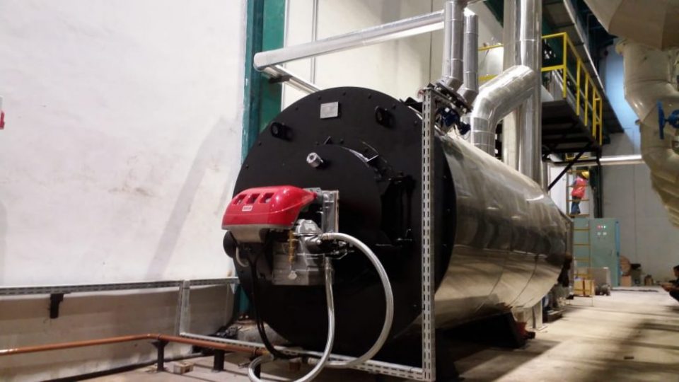
Secara khusus, artikel ini menjelaskan tentang preheater udara pembakaran yang digunakan pada boiler besar yang ditemukan di pembangkit listrik tenaga panas yang menghasilkan tenaga listrik dari bahan bakar fosil, biomassa atau limbah.

Superheater, Economiser and Air Preheater

Tujuan Preheaters
Tujuan preheater udara adalah untuk memulihkan panas dari gas buang boiler yang meningkatkan efisiensi termal boiler dengan mengurangi panas yang berguna yang hilang dalam gas buang.

Sebagai akibatnya, gas buang juga dibawa ke cerobong gas cerobong (atau cerobong asap) pada suhu yang lebih rendah, yang memungkinkan disederhanakannya desain sistem pengangkutan dan cerobong gas cerobong asap. Ini juga memungkinkan kontrol atas suhu gas yang meninggalkan tumpukan (untuk memenuhi peraturan emisi, misalnya).

Jenis Preheater Udara
Ada dua jenis preheater udara untuk digunakan dalam generator uap di pembangkit listrik termal: Satu adalah tipe tubular yang dibangun ke dalam saluran gas buang boiler, dan yang lainnya adalah preheater udara regeneratif. Ini dapat diatur sehingga gas mengalir secara horizontal atau vertikal melintasi sumbu rotasi.

1. Preheater Udara Jenis Tubular
Preheater berbentuk tabung terdiri dari bundel tabung lurus yang melewati saluran keluar dari boiler dan terbuka di setiap ujung di luar saluran tersebut. Di dalam ducting, gas tungku panas melewati tabung preheater, memindahkan panas dari gas buang ke udara di dalam preheater. Udara sekitar didorong oleh kipas melalui ducting di satu ujung tabung preheater dan di ujung lainnya udara panas dari dalam tabung muncul ke set ducting lain, yang membawanya ke tungku boiler untuk pembakaran.

2. Rotating-Plate Regenerative Air Preheater

Desain pelat-putar (RAPH) terdiri dari elemen pelat-putar pusat yang dipasang di dalam selubung yang terbagi menjadi dua (tipe bi-sektor), tiga (tipe tri-sektor) atau empat (tipe sektor quad) sektor yang mengandung seal sekitar elemen. Segel memungkinkan elemen untuk berputar melalui semua sektor, tetapi menjaga kebocoran gas antar sektor ke minimum sambil memberikan udara gas terpisah dan jalur gas buang melalui masing-masing sektor.

Jenis tri-sektor adalah yang paling umum dalam fasilitas pembangkit listrik modern. Dalam desain tri-sektor, sektor terbesar (biasanya mencakup sekitar setengah penampang selubung) terhubung ke outlet gas panas boiler.

Gas buang panas mengalir di atas elemen pusat, memindahkan sebagian panasnya ke elemen, dan kemudian disalurkan untuk perawatan lebih lanjut dalam pengumpul debu dan peralatan lainnya sebelum dikeluarkan dari tumpukan gas buang.

Sektor kedua, yang lebih kecil, diumpankan dengan udara sekitar oleh kipas, yang melewati elemen yang dipanaskan saat berputar ke sektor tersebut, dan dipanaskan sebelum dibawa ke tungku boiler untuk pembakaran. Sektor ketiga adalah yang terkecil dan memanaskan udara yang dialirkan ke pulverizer dan digunakan untuk membawa campuran batubara-udara ke pembakar boiler batubara.

Jadi, total udara yang dipanaskan dalam RAPH menyediakan: udara panas untuk menghilangkan kelembaban dari debu batu bara bubuk, udara pembawa untuk mengangkut batu bara bubuk ke pembakar ketel dan udara utama untuk pembakaran. Rotor itu sendiri adalah media perpindahan panas dalam sistem ini, dan biasanya terdiri dari beberapa bentuk baja dan / atau struktur keramik.

Berputar cukup lambat (sekitar 3-5 RPM) untuk memungkinkan perpindahan panas yang optimal. Dalam desain ini seluruh casing preheater udara didukung pada struktur pendukung ketel itu sendiri dengan sambungan ekspansi yang diperlukan dalam saluran. dan biasanya terdiri dari beberapa bentuk baja dan / atau struktur keramik. Berputar cukup lambat (sekitar 3-5 RPM) untuk memungkinkan perpindahan panas yang optimal.

Dalam desain ini seluruh casing preheater udara didukung pada struktur pendukung ketel itu sendiri dengan sambungan ekspansi yang diperlukan dalam saluran. dan biasanya terdiri dari beberapa bentuk baja dan / atau struktur keramik. Berputar cukup lambat (sekitar 3-5 RPM) untuk memungkinkan perpindahan panas yang optimal.

Dalam desain ini seluruh casing preheater udara didukung pada struktur pendukung ketel itu sendiri dengan sambungan ekspansi yang diperlukan dalam saluran.

Rotor vertikal didukung pada bantalan dorong di ujung bawah dan memiliki pelumasan penangas minyak, didinginkan oleh air yang bersirkulasi dalam gulungan di dalam penampung minyak.

Susunan ini untuk mendinginkan ujung bawah poros, karena ujung rotor vertikal ini berada pada ujung panas ducting. Ujung atas rotor memiliki bantalan rol sederhana untuk menahan poros pada posisi vertikal.

Rotor dibangun pada poros vertikal dengan penyangga radial dan sangkar untuk menahan keranjang pada posisinya. Pelat seal radial dan sirkumferensial juga disediakan untuk menghindari kebocoran gas atau udara di antara sektor-sektor atau antara saluran dan casing saat diputar.

Untuk pembersihan saluran endapan secara langsung dari keranjang uap disediakan sedemikian rupa sehingga debu dan abu yang tertampung dikumpulkan pada hopper abu dasar dari pemanas awal udara. Hopper debu ini terhubung untuk mengosongkan bersama dengan gerbong debu utama dari pengumpul debu.

Rotor diputar oleh motor yang digerakkan udara dan gearing, dan diperlukan untuk memulai sebelum memulai boiler dan juga harus disimpan dalam rotasi untuk beberapa waktu setelah boiler dihentikan, untuk menghindari ekspansi dan kontraksi yang tidak merata yang mengakibatkan lengkungan atau retaknya rotor.

Udara stasiun umumnya benar-benar kering (udara kering diperlukan untuk instrumentasi), sehingga udara yang digunakan untuk menggerakkan rotor disuntikkan dengan minyak untuk melumasi motor udara. Jendela inspeksi yang dilindungi keselamatan disediakan untuk melihat operasi internal preheater dalam semua kondisi operasi.

Keranjang berada di rumah sektor yang disediakan pada rotor dan dapat diperbarui. Umur keranjang tergantung pada abrasivitas abu dan sifat korosif gas outlet boiler.

Apa yang bisa dilakukan ASPL
Kami memperkenalkan diri sebagai salah satu Perusahaan Teknik terkemuka, membuat suku cadang untuk preheater udara seperti semua suku cadang pengganti APH, elemen keranjang baik elemen yang tidak diemail dan elemen diemail, Stempel, Tbar, peredam kecepatan dll. Kami telah memasang dalam pekerjaan kami di Chennai mesin-mesin diperlukan untuk pembuatan semua jenis keranjang APH.

Bagi kami mengutip anggaran untuk pekerjaan keranjang atau pekerjaan segel, kami membutuhkan item berikut untuk setiap persyaratan:
Jumlah pemanas udara Ukuran dan jenis pemanas udara (yaitu 32,5 VI)
Apakah pemanas udara modular atau tidak
Jumlah diafragma (12, 24 , 36 atau 48)
Preheater udara Nomor kontrak (jika diketahui)
Nomor preheater udara individu (jika diketahui)

Untuk kutipan keranjang, kita perlu tahu lapisan mana yang akan dikutip (panas, menengah, dingin, dll.):

Untuk Setiap Lapisan Individu kita perlu tahu:

o Profil elemen (yaitu CU, DL, DN, DU, DL7, DN7, DU7, NF6)
o Jenis bahan elemen (yaitu CorTen Grade A, B, C; ASTM A606 tipe 4; ASTM A606 tipe 2; ASTM 1008; dll.)
O Gauge bahan
o Kedalaman lapisan elemen
o Enamel (Y / N)

Gambar dengan dimensi yang diperlukan untuk penawaran keranjang:
Gambar Perakitan Modul (jika pemanas udara modular)
Perakitan Rotor Gambar
Keranjang Pengaturan Gambar untuk setiap lapisan yang dikutip

Jika kita mengutip segel, kita perlu:
Untuk mengetahui rotasi pemanas udara dari sisi panas (sisi gas).
Gambar Rakitan Segel Radial dengan dimensi.

Segera setelah Anda dapat mengembalikan informasi ini untuk setiap persyaratan, kami dapat menyiapkan penawaran anggaran. Jika Anda memiliki persyaratan khusus, silakan kirimkan pertanyaan Anda, dengan menyebutkan deskripsi lengkap tentang barang-barang yang diperlukan untuk Air Preheater.

Aksesori ketel adalah perangkat bantu yang dipasang di dalam atau di luar ketel. Aksesori ketel digunakan untuk meningkatkan efisiensi ketel dan untuk memfungsikan ketel. Asesoris berikut umumnya digunakan dalam boiler:

Superheater, Economiser and Air Preheater

(a) Economiser

(b) Air preheater

(c) Superheater

(d) Feed pump

(i) Duplex

(ii) Injector

(e) Steam trap

(f) Steam separator

(g) Pressure reducing valve.

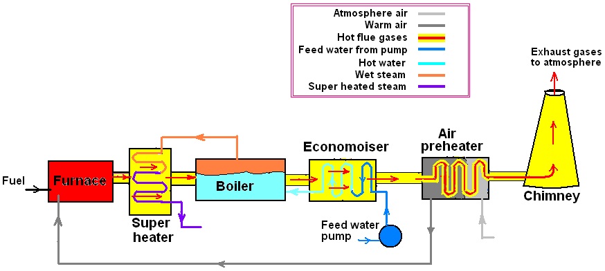
30.1. Posisi Relatif dari Superheater, Economiser dan Air Preheater
Posisi relatif pre-heater udara, economiser, dan superheater ditunjukkan pada Gambar 30.1.

Gbr. 30.1. Posisi Relatif dari Superheater, Economiser, dan Pra-pemanas Udara.

30.2. Simpan

Fungsi: Fungsi economiser adalah mengekstraksi panas yang terbawa oleh gas buang di cerobong atau tumpukan dan menggunakannya untuk memanaskan air umpan yang dipasok ke boiler.

Lokasi: Ditempatkan di jalur gas buang di antara pintu keluar dari boiler dan masuk ke preheater / cerobong udara (Gambar 30.1 dan Gambar 30.2).

Gbr. 30.2. Boiler Lancashire dilengkapi dengan economiser

Mengapa perangkat ini disebut Economiser daripada Feed Water Pre-heater?

Karena suhu air umpan dinaikkan sebelum disuplai dalam boiler dengan penggunaan economiser, air dalam boiler membutuhkan lebih sedikit panas untuk dikonversi menjadi uap. Ini menghasilkan penghematan bahan bakar yang meningkatkan ekonomi pabrik boiler. Karena pemulihan panas tambahan meningkatkan ekonomi pabrik boiler, maka namanya diberikan sebagai economizer alih-alih feed water pre-heater.

Persentase penghematan dalam konsumsi bahan bakar diberikan oleh

S =

Di mana, S = persentase penghematan dalam konsumsi bahan bakar

t 2 = suhu air umpan di outlet economizer, ° C

t 1 = suhu air umpan pada inlet economizer, ° C

h g = entalpi uap kering pada tekanan boiler, kJ / kg

h sub, 1 = entalpi air pada t 1 ° C, kJ / kg

C p = panas spesifik air, kJ / KGK

Konstruksi:

Economizer Green yang digunakan dengan boiler stasioner ditunjukkan pada Gambar 30.3 bersama dengan detail konstruksinya. Ini terdiri dari sekelompok tabung besi cor vertikal yang dipasang antara header atas dan bawah. Untuk keamanan terhadap tekanan tinggi, katup pengaman dipasang di bagian atas header.

Seperti ketel, ia memiliki blow down valve yang dipasang di bagian bawah untuk mengeluarkan sedimen yang dikumpulkan di bagian bawah economizer. Scrapers disediakan pada tabung untuk menghilangkan jelaga gas buang yang diendapkan pada tabung economiser. Dengan demikian jelaga yang dikeluarkan dari tabung dikumpulkan dalam ruang yang disediakan di bagian bawah economizer. Dua katup penghenti, satu di tajuk bawah dan yang lainnya di tajuk atas, masing-masing disediakan untuk menghentikan atau membiarkan air masuk dan keluar dari economizer.

Operasi :

Air umpan dari pompa umpan masuk terlebih dahulu ke header bawah economizer sebelum masuk ke boiler. Dari tajuk bawah air kemudian melewati tabung vertikal dan mencapai ke tajuk atas, dari mana akhirnya mengarah ke boiler. Pada saat yang sama gas buang bergerak di sekitar tabung dan mengeluarkan panasnya ke air yang mengalir di dalam tabung vertikal dan dengan demikian air dipanaskan dalam economizer.

Sementara economizer dalam pengoperasian pemanas air, pengikis yang disediakan pada tabung dipindahkan ke atas dan ke bawah terus-menerus dengan bantuan pengaturan rantai dan roda gigi sehingga jelaga yang disimpan di pipa dapat dihilangkan dan efisiensi maksimum dari economizer dapat dicapai sebagai jelaga deposit pada pipa mengurangi perpindahan panas ke air.

Gbr. 30.3. Green’s Economiser

Pengaturan by-pass seperti yang ditunjukkan pada Gambar. 30.4 disediakan untuk mengisolasi economiser ketika tidak diperlukan atau ketika akan dibersihkan atau diperbaiki. Saat economiser beroperasi, damper A ditutup sementara damper B dan C dibuka. Ketika economiser tidak beroperasi maka damper B dan C ditutup dan damper A harus dibuka.

Gbr. 30.4. Pengaturan by-pass dari economiser di boiler Lancashire

Keuntungan seorang ahli ekonomi:

(i) Meningkatkan efisiensi termal dari pabrik boiler dengan memanfaatkan limbah panas, menghemat bahan bakar.

(ii) Air umpan panas menyebabkan peningkatan kapasitas penguapan.

(iii) Umur yang lebih lama dari ketel karena ini mengurangi perbedaan suhu antara berbagai bagian ketel

(iv) Sejumlah besar pengotor pembentuk skala dapat dihilangkan oleh presipitasi karena pemanasan awal air umpan.

(v) Gas terlarut seperti udara atau CO 2 juga dapat dihilangkan dengan pemanasan awal air umpan, mengurangi korosi dan lubang.

Kerugian:

Ini mengurangi draft alami karena menghalangi saluran gas buang.

Masalah 30.1: Hitung persentase penghematan bahan bakar dengan memasang economizer dengan boiler jika uap meninggalkan boiler kering dan jenuh pada 13 bar. Air umpan masuk ke economizer pada 40 ° C dan pergi pada 125 ° C.

Larutan:

Diberikan: Tekanan uap dalam boiler = p = 13 bar

Dari tabel uap, untuk uap pada tekanan, p = 13 bar

t s = 191,60 ° C. h f = 814,59 h g = 2785,7 kJ / kg

Air umpan masuk ke economizer pada suhu, t i = 40 ° C

Air umpan meninggalkan economizer pada suhu, t e = 125 ° C.

Tentukan persentase penghematan bahan bakar dengan memasang economizer dengan boiler:

Formula: Menghemat bahan bakar = x100

Menemukan tidak diketahui,

Panas dihemat dengan memanaskan 1 kg air umpan sebelumnya di economizer,

= m Cp (t e –t i ) = 1 x 4,18 x (125 – 40) = 355,3 kJ / kg

Panas diperlukan untuk mengubah 1 kg air pada suhu 40 ° C menjadi uap jenuh kering pada suhu 13 bar

= h g – h sub = m Cp (t s –t i ) + (h g – h f ).

= 1 x 4,18 x (191,60 – 40) + (2785,7 – 814,59)

= 633,69 + 1971.11 = 2604,8 kJ / kg

Jawab: Menghemat bahan bakar = x 100

× 100 = 13.6%

30.3. Preheater Udara

Fungsi: Seperti economizer, pemanas awal udara juga memulihkan sebagian panas limbah dari gas cerobong / cerobong asap dan menggunakannya untuk pemanasan awal udara yang disuplai ke ruang bakar boiler.

Lokasi: Preheater udara biasanya ditempatkan setelah economiser dan sebelum gas memasuki cerobong asap seperti yang ditunjukkan pada Gambar 30.1.

Konstruksi dan operasi:

Preheater udara dapat diklasifikasikan sebagai tipe tubular, tipe pelat, dan tipe regeneratif:

(i) Jenis tubular: Jenis tubular yang biasa digunakan di pabrik boiler yang lebih kecil ditunjukkan pada Gambar 30.5. Gas panas dilewatkan melalui tabung dan udara dipaksa mengalir di atas tabung.

Untuk meningkatkan periode kontak antara udara dan permukaan panas sehingga udara dipanaskan secara efektif, udara dipaksa untuk membelokkan dengan menggunakan baffle dan dipaksa untuk bergerak di jalur zigzag beberapa kali. Jelaga dan material lain yang dibawa dengan gas dikumpulkan di hopper di bagian bawah dan dibuang secara berkala melalui gerbang jelaga.

Gbr. 30.5. Preheater Udara Tubular

(ii) Jenis pelat : Pada preheater ini, saluran gas dan udara alternatif dibentuk antara pelat paralel yang berjarak dekat. Udara mengalir melalui ruang alternatif pelat paralel ini dan gas buang melewati bagian-bagian yang tersisa seperti yang ditunjukkan pada Gambar. 30.6.

Gbr. 30.6. Piring-preheater udara

(iii) Jenis regeneratif: Gas buang panas dan udara dibuat untuk mengalir secara alternatif melalui jalur yang sama yang terdiri dari wire mesh seperti yang ditunjukkan pada Gambar 30.7. Gas buang panas dibuat untuk melewati wire mesh dengan membuka katup 1 & 4 dan menutup katup 2 & 3.

Saat melewati wire mesh, gas buang panas menolak dan menyimpan panasnya ke dalam wire mesh. Pada pass alternatif, ketika udara atmosfer melewati wire mesh dengan membuka katup 2 & 3 dan menutup katup 1 & 4, ia menerima panas dari wire mesh dan akibatnya udara menjadi panas.

Gambar 30.7. Regenerative-preheater

Keuntungan dari pemanasan awal udara :

(1) Limbah panas dari gas buang dipulihkan untuk memanaskan udara dan menyebabkan penghematan bahan bakar sekitar 1,5% untuk setiap penurunan suhu gas 100 ° C.

(2) Batubara kualitas rendah dapat dibakar secara efisien dengan udara yang dipanaskan.

(3) Diperlukan lebih sedikit udara berlebih untuk membakar bahan bakar dan dengan demikian biaya pembuatan konsep akan lebih sedikit.

(4) Pembakaran bisa lebih efisien dan nyala api yang intens dapat dicapai dalam tungku. Ini meningkatkan tingkat penguapan boiler.

Kekurangan:

(i) Peningkatan modal dan biaya pengoperasian pemanas awal sebagai kipas angin terinduksi untuk mengeluarkan gas dan kipas paksa untuk memaksa udara dingin melalui pemanas udara sebelumnya digunakan.

Masalah 30.2 : Bahan bakar yang digunakan dalam boiler memiliki nilai kalor 25120 kJ / kg. Suhu gas yang meninggalkan ruang economizer adalah 260 ° C dan dikurangi menjadi 150 ° C saat meninggalkan ruang pra-pemanas.

Jika 18 kg udara disuplai per kg batu bara yang terbakar dan efisiensi pra-pemanas adalah 80% menentukan (a) persentase penghematan panas batu bara di pra-pemanas, (b) suhu udara yang meninggalkan pra-pemanas pemanas jika suhu awal udara adalah 27 ° C. Ambil Cp udara dan gas buang sama dengan 1,05 kJ / kg.

Larutan:

Diberikan: Nilai kalor bahan bakar yang digunakan dalam boiler = 25120 kJ / kg

Temperatur gas meninggalkan economiser dan memasuki pra-pemanas, tg , i = 260 ° C

Suhu gas meninggalkan pra-pemanas, tg , e = 150 ° C

Suhu udara memasuki pra-pemanas, t a, i = 27 ° C

Efisiensi pra-pemanas, η cp = 80%

Massa udara disuplai ke tungku boiler per kg batubara yang terbakar = 18 kg

C p dari udara dan gas buang = 1,05 kJ / kg.

(a) Tentukan persentase penghematan panas batubara di pre-heater:

Formula: Persentase penghematan panas batu bara di pre-heater

=

Menemukan tidak diketahui,

Panas dipindahkan ke udara dalam pre-heater per kg batubara dibakar = m f .C p . (T e t i ). η cp

Menemukan yang tidak diketahui, m f;

Massa gas buang / kg batu bara, m f = massa batu bara + massa udara

= 18 + 1 = 19 kg

Oleh karena itu, panas yang ditransfer ke udara di pre-heater = m f .C p . ( Tg, e -t g, i ). η cp

= 19 x 1,05 x (260 – 150) x 0,8

= 1755,6 kJ / kg

Jawab: Persentase penghematan panas batu bara di pre-heater

=

= = 6.988%

(B) Tentukan suhu udara meninggalkan pra-pemanas

Biarkan t a, e ° C menjadi suhu udara yang meninggalkan preheater.

Formula: Panas yang ditransfer oleh gas di pre-heater = Panas yang didapat melalui udara

= m a .C hal . (t a, e – t a, i )

Jawab: Panas ditransfer oleh gas ke udara di pre-heater = m a .C p . (t a, e – t a, i )

1755.6 = 18 x 1.05 (t a, e – 27)

atau t a, e = 119.888 ° C

30.4. Steam superheater

Fungsi: Dalam pemanas super, uap kering basah atau jenuh dipanaskan dengan meningkatkan suhu uap di atas suhu saturasinya.

Lokasi: Superheater dipasang di jalur gas buang setelah tungku seperti yang ditunjukkan pada Gambar 30.1. Kadang-kadang, untuk boiler yang lebih besar, superheater dapat ditempatkan di tungku api independen.

Konstruksi dan operasi:

Ini terdiri dari satu set tabung melalui mana uap kering basah atau jenuh mengalir dan gas pembakaran panas melewati tabung-tabung ini. Dengan cara ini, uap kering basah atau jenuh mengambil panas dari gas buang dan menjadi super panas.

Klasifikasi Superheaters:

Menurut mode penerimaan panas:

(i) Konveksi pemanas super,

(ii) Superheater radiasi dan

(ii) Kombinasi superheaters

seperti yang ditunjukkan pada Gambar. 30.8.

(i) Superheater konvektif: Dalam superheater konvektif, superheater ditempatkan di antara atau di dekat tabung air tempat tabung superheater menerima panas melalui konveksi dari gas pembakaran.

(ii) Superheater tipe radiasi: Dalam superheater radiasi, superheater ditempatkan di dinding tungku ketel uap tempat tabung superheater menerima panas oleh radiasi langsung dari api dan radiasi ulang dari dinding refraktori.

(iii) Jenis kombinasi: Dalam superheater gabungan, uap pertama-tama memasuki superheater yang berseri-seri dan kemudian superheater konvektif. Dalam panas ini pembakaran dipindahkan ke tabung superheater oleh radiasi dan kemudian konveksi.

Gbr. 30.8. Posisi superheater Konvektif, berseri dan kombinasi.

Menurut pergerakan gas dan uap:

Ada jenisnya

(i) Aliran paralel,

(ii) Counterflow dan

(iii) Aliran gabungan

seperti yang ditunjukkan pada Gambar. 30.9 (a, b, c).

(i) Superheater aliran paralel: Gas buang panas dan uap basah mengalir ke arah yang sama.

(ii) Counter flow superheater: Gas buang panas dan uap basah mengalir ke arah yang berlawanan.

(iii) Superheater aliran kombinasi: Gas buang panas dan uap basah pertama-tama mengalir ke arah yang berlawanan dan kemudian ke arah yang sama.

Dari klasifikasi di atas, counter flow superheater biasa digunakan karena ukurannya yang lebih kecil, bobotnya lebih ringan, dan efisiensi maksimum.

Gbr. 30.9. (a) Aliran paralel, (b) Aliran balik dan (c) Aliran panas kombinasi

Menurut pengaturan tabung superheater:

(i) Overdeck. Ini ditempatkan di ruang di atas tabung air seperti yang ditunjukkan pada Babcock & Wilcox boiler pada Gambar 28.3.

(ii) Interdeck. Ini ditempatkan di antara tabung air yang terletak di dekat tungku.

(iii) Intertubes. Ini ditempatkan di antara bank atau deretan tabung air.

Keuntungan:

Manfaat berikut diperoleh dengan memanaskan uap dalam superheaters:

(1) Ini mengurangi konsumsi uap spesifik dari mesin uap atau turbin.

(2) Ini mengurangi kerugian kondensasi dalam pipa uap dan silinder mesin uap.

(3) Ini menghilangkan erosi bilah turbin.

(4) Efisiensi pembangkit uap meningkat.

30.5. Pompa Pakan

Fungsi:

Fungsi pompa umpan adalah untuk memompa air umpan ke dalam ketel terhadap tekanan ketel.

Klasifikasi pompa umpan:

Tiga jenis pompa umpan yang biasa digunakan adalah

(i) Rotary,

(ii) Reciprocating dan

(iii) Injector.

(i) Pompa putar: Jenis pompa ini digunakan ketika sejumlah besar air umpan akan dipasok ke boiler. Ini umumnya jenis sentrifugal kecepatan tinggi yang digerakkan oleh motor listrik atau turbin uap kecil yang dijalankan oleh uap dari boiler yang sama yang digunakan untuk mengalirkan air.

(ii) Pompa reciprocating: Pompa feed Duplex yang ditunjukkan pada Gambar 30.10 adalah jenis pompa reciprocating yang umum digunakan untuk boiler ukuran sedang.

Konstruksi dan pengoperasian pompa umpan Duplex dijelaskan di bawah ini:

Ini adalah pompa umpan kerja ganda. Ini terdiri dari dua pompa, yaitu pompa air dan pompa uap, dipasang berdampingan. Kedua pompa memiliki silinder sendiri.

Piston kedua silinder terhubung ke batang pistonnya sendiri yang akhirnya terhubung ke kepala silang umum sehingga pompa uap berfungsi sebagai penggerak pompa air karena perluasan uap pada silinder uap.

Di pompa uap, katup geser D, digerakkan oleh kepala silang umum dari dua silinder, digunakan untuk mengontrol pemasukan dan pembuangan uap dalam silinder uap sedangkan di pompa air, katup pengisapan dan katup pengiriman yang dioperasikan otomatis digunakan untuk pemasukan dan pengeluaran umpan air dalam silinder air. Untuk pasokan air umpan terus menerus pada tekanan tinggi,

Gbr. 30.10. Pompa pakan duplex

(iii) Injektor : Injektor adalah jenis lain dari pompa umpan di mana energi jet uap digunakan untuk memasukkan air ke dalam boiler. Sangat cocok untuk boiler kecil atau di mana ruang tidak tersedia untuk pemasangan umpan pompa pakan seperti dalam kasus boiler Lokomotif. Biaya perawatannya lebih sedikit dan secara termal sangat efisien karena uap yang diperlukan untuk mengoperasikan injektor dikembalikan ke boiler.

30.6. Steam Trap

Fungsi: Fungsi steam trap adalah untuk mengalirkan sebagian air yang terkondensasi dari pipa steam tanpa membiarkan uap keluar melalui itu.

Lokasi: diatur dalam pipa uap di dekat mesin atau turbin.

Jenis steam traps:

Perangkap uap terdiri dari dua jenis:

(i) Tipe bucket atau float

(ii) Jenis ekspansi termal.

30.7. Pemisah Uap

Fungsi: Fungsi pemisah uap adalah untuk memisahkan partikel air yang tersuspensi yang dibawa oleh uap dalam perjalanan dari boiler ke mesin atau turbin tanpa membiarkan uap keluar melalui itu.

Lokasi: Ini dipasang di pipa uap utama sangat dekat dengan mesin atau turbin.

Konstruksi dan operasi:

Lihat Gambar. 30.11. Uap dari boiler memasuki separator uap melalui flensa ‘A’ dan mengalir ke bawah. Selama perjalanan turun, ia menyerang baffle dan mengubah arahnya. Ketika mengubah arah, parsial air yang ditangguhkan dalam uap jatuh ke dasar pemisah karena inersia yang lebih besar dan uap kering yang dialirkan keluar keluar melalui flensa ‘B’. Air yang dikumpulkan di bagian bawah dikeringkan oleh pengaturan saluran air. Gelas pengukur air dipasang di pemisah untuk melihat tingkat air di pemisah.

Gbr. 30.11. Pemisah Uap

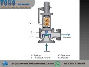
30.8. Katup Pengurangi Tekanan

Fungsi: Fungsi katup penurun tekanan adalah untuk memasok uap pada tekanan konstan pada sisi pengirimannya dengan mencekik pasokan uap yang tidak konsisten dari boiler pada sisi saluran masuknya.

Lokasi: Katup penurun tekanan dipasang di pipa pasokan uap untuk memasok uap tekanan konstan lebih rendah dari tekanan boiler yang dibutuhkan oleh penggerak utama.

Konstruksi dan operasi:

Gambar 30.12 menunjukkan katup penurun tekanan. Steam tekanan tinggi dari boiler memasuki flens inlet steam. Setelah masuk ke dalam katup penurun tekanan, steam melewati katup throttle di mana ia di-throttle ke tekanan yang dibutuhkan rendah dan karenanya uap di outlet katup pengurang tekanan dicapai pada tekanan yang dikurangi. Untuk mencapai tekanan yang diperlukan yang dikurangi di outlet katup, katup yang digerakkan digerakkan oleh pegas dan mekanisme batang katup disesuaikan sesuai dengan sekrup penyesuaian F.


Coil oil Thermal boiler

Mencegah OIl Heater Oksidasi

Mencegah OIl Heater Oksidasi

Coil oil Thermal boiler
Coil oil Thermal fluid  boiler

THERMAL OIL HEATER TER OKSIDASI
Salah satu sebab yang paling mempengaruhi umur oli / pelumas adalah Oksidasi. Dalam pengertian sederhana, oksidasi adalah reaksi berantai yang melanda sebuah oli / pelumas sehingga sifat- sifat oli/ pelumas menjadi berubah. Perubahan tersebut antara lain: berubahnya kekentalan, ke asaman, warna, dan pada kasus terparah adalah munculnya deposit/lumpur/ varnish( pengerakan pada donding pipa thermal oil heater. Penggunaan aditif antioksidan dapat mengurangi terjadinya proses oksidasi namun ada hal-hal diluar oli/ pelumas yang dominan sebagai pemicu terjadinya oksidasi,

Pemicu terjadinya oksidasi pada thermal boiler adalah:

1. Panas.Over heat di bejana chember
Panas yang berlebih merupaka pemicu terjadinya oksidasi. Definisi panas disini adalah jika temperatur / suhu melebihi batas desain thermal oil boiler dari mesin itu sendiri. Umumnya, dalam aplikasi industri oli/ pelumas dijaga pada temperatur 60o Celcius diukur pada tangki. Aturan umumnya, setiap kenaikan 10o Celcius dari 60o Celcius akan mengurangi umur oli/ pelumas hingga setengahnya.

Oleh sebab itu aturan desain thermal fluida tidak disarankan oil terbakar dalam subuah chember tank terdiam tidak bersikulasi,
Sirkulasi thermal fluida pun di sarankan dengan desain turbular flas coil sepiral , desain tersebut sudah di teliti minimum 3 detik /6 meter
Untuk mencegah over heating di body chamber. Desain ini ang selalu di pakai oleh pt Indira dwi mitra untuk pembuatan thermal oil boiler.

2. Udara terperangkap .
Udara yang terperangkap dalam oli/ pelumas akan memicu terjadinya oksidasi bersamaan dengan kenaikan suhu. Udara biasanya masuk pada tangki melalui breather (lubang penting). Akibat tekanan pada pipa balik ke tangki fenomena pembuihan/ (foaming) akan terjadi.
Akibatnya udara terperangkap didalam oli/ pelumas dan memicu terjadinya oksidasi dan kavitasi/ hunting pada pompa heat transfer oil .
Penggunaan oli/ pelumas dengan sifat anti foaming yang baik dapat juga membantu mengurangi terperangkapnya udara dalam oli/ di bejana chamber boiler.

TIPS dari kami, untuk sistem pemindahan panas (heat transfer system) yang menggunakan oil boiler, pada saat initial fill pastikan tidak ada udara yang terperangkap ke dalam sistem pipa dengan bantuan venting di pipa. Hal ini sangat berpengaruh pada life tine /umur heat transfer oil tersebut.

3. Air bercampur dengan oil heater.
Selain panas dan udara, air merupakan pemicu terjadinya oksidasi yang sangat berbahaya. Air biasanya masuk melalui kondesasi pada tangki, kebocoran oil thermal dan kebocoran seal/ packing.
Air tidak hanya berbahaya pada oli / pelumas, namun juga berbahaya pada mesin yang di lumasi.
Ini disebabkan sifat pelumasan dari oli,menjadi berkurang sehingga mengakibatkan / penguapan /keausan pada mesin thermal boiler tersebut.

Air juga mengakibatkan kemampuan pelumas untuk difilter menjadi berkurang, terutama pada aplikasi peralatan presisi yang membutuhkan kerapatan filter yang tinggi.
TIPS dari kami, selalu periksa kebojoran pada sambungan pemipaan, selain itu periksa kondisi oli / pelumas
dan pilihlah oli/ pemasnas yang mempunyai kemampuan memisahkan diri dengan air yang baik serta daya tahan tinggi terhadap air.

4. Katalis Logam.
Beberapa logam dapat memicu terjadinya oksidasi, misalnya logam tembaga. Contoh peralatan yang memakai tembaga adalah main bearing dan oil cooler.